Latch assembly

a technology of latching and assembly, which is applied in the direction of cylinder locks, keys, mechanical equipment, etc., can solve the problems of long lock cylinders and locked areas

Active Publication Date: 2005-10-20
SOUTHCO
View PDF16 Cites 28 Cited by
  • Summary
  • Abstract
  • Description
  • Claims
  • Application Information

AI Technical Summary

Benefits of technology

[0019] The objects of the present invention are also realized in a lock cylinder configured for a key. Master key functionality is attained by adding an annular ring to the basic lock cylinder structure and modifying the profile of the low level security key. A separate key profile for each key is provided to provide the master key capability. A portion of one of the bits of the master key is machined deeper than the low level security key and has a key stop where the bit abuts the stem. When the lock cylinder is provided with a master annular ring, the lock cylinder can only be operated by the master key and not the limited access low level security key due to the presence of a tab on the master annular ring provided on the front of the lock cylinder which prevents entry of the limited access or low level security key into the lock cylinder. The master key can also operate the lock cylinder when the lock cylinder is fitted with a low level security annular ring which does not have the tab which is present on the master annular ring.

Problems solved by technology

In addition, it is oftentimes desired that the lock cylinder of latches generally have the capability of being opened with a master key in addition to a lower level security key.
However, there may be locked areas which are only to be accessible by the captain of the ship.
This resulted in very long lock cylinders which oftentimes would protrude from the back side of the door or panel due to the length of the lock cylinders.

Method used


Image

  • Latch assembly
  • Latch assembly
  • Latch assembly

Examples


first embodiment

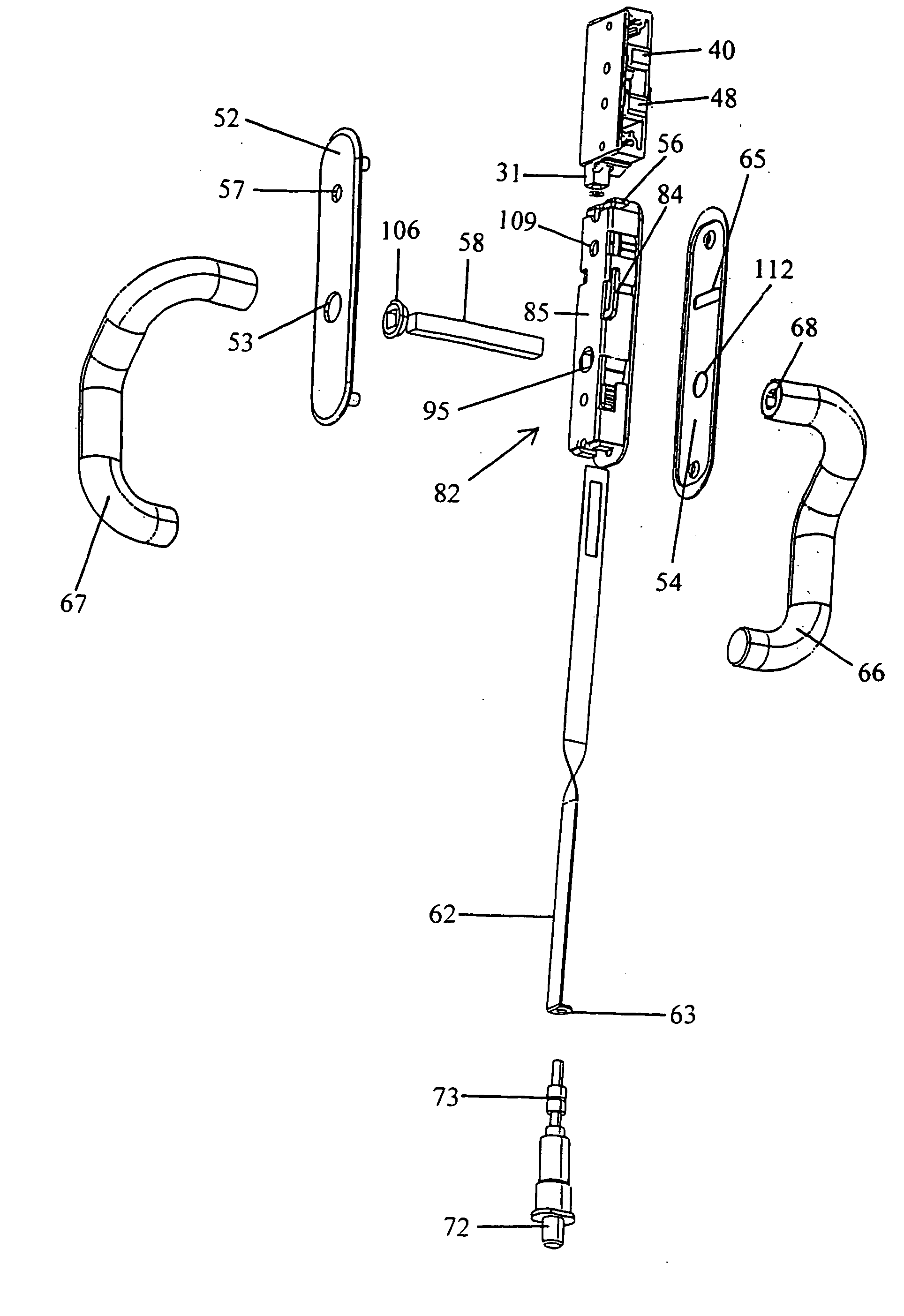
[0056] The latching means of the first embodiment also comprises a biasing means 38 which biases the pawl actuator 31 to the latched position. In the embodiment shown the biasing means is a coil spring 38 which acts upon the pawl actuator 31. The other end of the coil spring 38 presses against the bottom of the rotary latch rear cover piece 35 which can be held together with rotary latch front cover piece 39 by pins or screws which extend from rotary latch front cover piece apertures 44 to rotary latch rear cover piece apertures 36.

[0057] The pawl actuator 31 of the first embodiment can be inserted into pawl actuator groove 37 and has a notch 32 and the pawl actuator 31 has pawl actuator screw hole 34 for pawl actuator screw 33. Assembly of the rotary latch latching means can be made much easier and the coil spring 38 can be held in a compressed state more easily by the presence of latch elbow 45 which is screwed on at latch elbow connecting means (here an aperture 76) to the rotary...

second embodiment

[0058] The latch assembly of the present invention is shown in FIGS. 30 and 34 in the latched position fastened to a keeper 174 and the slide latch assembly is shown installed in FIG. 31 in a door 29. An exploded view of the latching means is shown in FIG. 32. The latching means comprises a single pawl actuator 131 and a single pawl 148 which is rotatable about single pawl pin 142. In the embodiment shown, the single pawl 148 has a single pawl claw 140. The single pawl 148 upon actuation of lever 151 by the single pawl actuator 131 rotates such that the single pawl 148 moves to a latched position and engages the keeper 174 shown in FIG. 30.

[0059] The latching means also comprises a biasing means 38 which biases the single pawl actuator 131 to the latched position. In the embodiment shown the biasing means is a coil spring 38 which acts upon the single pawl actuator 131. In the embodiment shown, the coil spring acts upon a face of the single pawl actuator. The other end of the coil s...


PUM


Abstract

A latch assembly having a keyless toggle lock capability and capable of being unlocked by either a low level security key or a master key. When a user rotates the front handle or rear handle the actuator of the latch assembly provides for sliding movement of a sliding element so as to provide for actuation of a latching means.

Description

BACKGROUND OF THE INVENTION [0001] The present invention relates generally to latch assemblies. [0002] Latch assemblies are known in the art and are provided for the latching and the opening of a member such as a door or panel. [0003] In addition, it is oftentimes desired that the lock cylinder of latches generally have the capability of being opened with a master key in addition to a lower level security key. This is particularly true in the case of marine applications where the individual members of a crew need access to individualized areas which the captain of the vessel also needs access to. However, there may be locked areas which are only to be accessible by the captain of the ship. In such cases, the captain would need a high level security key or master key to access his areas and also the crews areas. [0004] In many prior art lock cylinders, the door or panel in which the lock cylinder was installed needed to be as thick as a significant portion of the length of the key wh...

Claims


Application Information

Patent Timeline
Patent Type & Authority Applications(United States)
IPC IPC(8): E05B19/00E05B27/00E05B29/00E05B35/04E05B35/10E05B63/00E05B63/04E05B63/12E05B63/14E05B65/08E05C3/10E05C3/16E05C3/34E05C9/02E05C9/18
CPCE05B19/0047E05B35/10E05B63/0069E05B63/04E05B63/12E05B63/143E05C9/10E05B65/0858E05B65/0876E05C3/10E05C3/34E05C9/1875E05C9/026E05B65/0811Y10T70/5226Y10T292/0839E05C3/165E05C9/02
Inventor JOHANSSON, TORSTENMAGNUSSON, CLAES
Owner SOUTHCO
Why Eureka
Try Eureka