Triangle identification buffer

a triangular and buffer technology, applied in the field of triangular identification buffers, can solve the problems of large amounts of texture data unnecessarily being retrieved and written to the color buffer,

Inactive Publication Date: 2005-10-20
STMICROELECTRONICS LTD
View PDF15 Cites 29 Cited by
  • Summary
  • Abstract
  • Description
  • Claims
  • Application Information

AI Technical Summary

Problems solved by technology

Whilst it provides technically useful results, the use of a depth buffer in this fashion often resu

Method used


Image

  • Triangle identification buffer
  • Triangle identification buffer
  • Triangle identification buffer

Examples


Embodiment Construction

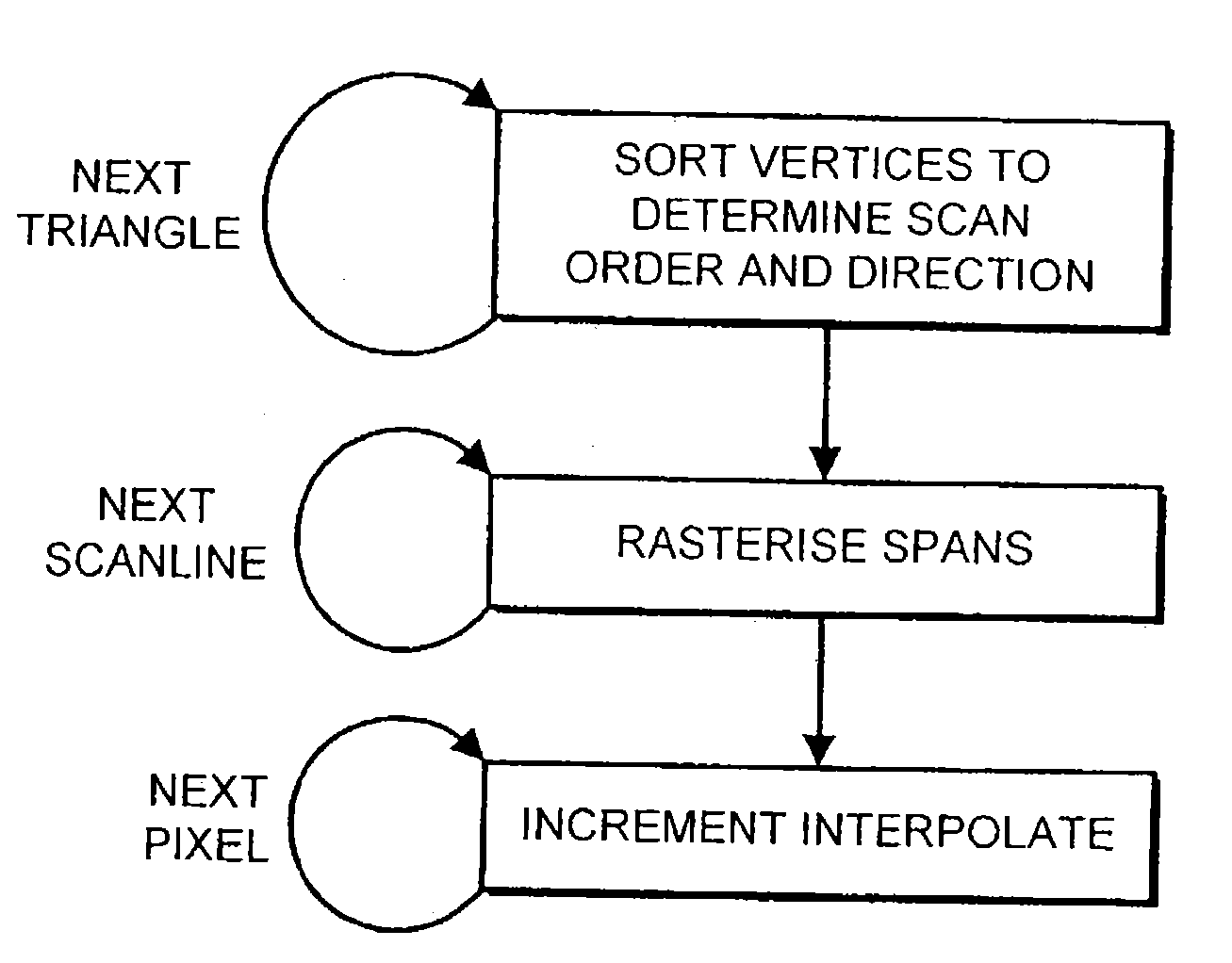
[0040] Embodiments of a triangle identification buffer are described herein. In the following description, numerous specific details are given to provide a thorough understanding of embodiments of the invention. One skilled in the relevant art will recognize, however, that the invention can be practiced without one or more of the specific details, or with other methods, components, materials, etc. In other instances, well-known structures, materials, or operations are not shown or described in detail to avoid obscuring aspects of the invention.

[0041] Reference throughout this specification to “one embodiment” or “an embodiment” means that a particular feature, structure, or characteristic described in connection with the embodiment is included in at least one embodiment of the present invention. Thus, the appearances of the phrases “in one embodiment” or “in an embodiment” in various places throughout this specification are not necessarily all referring to the same embodiment. Furt...


PUM


Abstract

A method of rendering a plurality of triangles into a color buffer defined by a plurality of pixel locations, utilizing a triangle identification buffer and a depth buffer. A relatively unique identifier is assigned to each of the triangles to be rendered. Before color and texture mapping, each triangle is depth compared on a per pixel basis. If a pixel of a current triangle is in front of any existing pixel at that point, the current triangles identifier is over-written into a triangle identification buffer. Color texture data is only retrieved for each triangle that appears in the identification buffer once all triangles have been compared.

Description

BACKGROUND OF THE INVENTION [0001] 1. Field of the Invention [0002] The present disclosure relates generally to graphical manipulation of objects defined in three-dimensional space, and more particularly but not exclusively, to the rendering of such objects into a color buffer for subsequent display on a two-dimensional screen such as a computer monitor. [0003] One embodiment of the invention has been developed primarily for use in graphics chips where speed and throughput of rendered polygons is paramount, and will be described hereinafter with reference to this application. However, it will be appreciated that the invention is not limited to use in this field. [0004] 2. Description of the Related Art [0005] The market for “3D” accelerator video cards for PCs and other computing platforms has grown drastically in recent years. With this growth has come an increasing desire for faster accelerator chips incorporating an increasing number of features such as realistic lighting models ...

Claims


Application Information

Patent Timeline
IPC IPC(8): G06T15/40
CPCG06T15/405
Inventor SIMPSON, ROBERTHUSSAIN, ZAHID
Owner STMICROELECTRONICS LTD
Why Eureka
Try Eureka