Histograms, trends and spectrums of random and deterministic jitter

a random and deterministic jitter, trend and spectrum technology, applied in the direction of signal quality detector, error detection/prevention using signal quality detector, transmission monitoring, etc., can solve the problem of circuits that behave improperly, digital signals are unusable, and increase the bit error rate of a communication signal

Inactive Publication Date: 2005-10-20
WARD BENJAMIN A +2
View PDF4 Cites 15 Cited by
  • Summary
  • Abstract
  • Description
  • Claims
  • Application Information

AI Technical Summary

Problems solved by technology

Jitter in digital signals, if large enough, can render the digital signals unusable as the values of data units within the signal become ambiguous.
For example excessive jitter may increase the bit error rate (BER) of a communication signal by cau...

Method used


Image

  • Histograms, trends and spectrums of random and deterministic jitter
  • Histograms, trends and spectrums of random and deterministic jitter
  • Histograms, trends and spectrums of random and deterministic jitter

Examples


Embodiment Construction

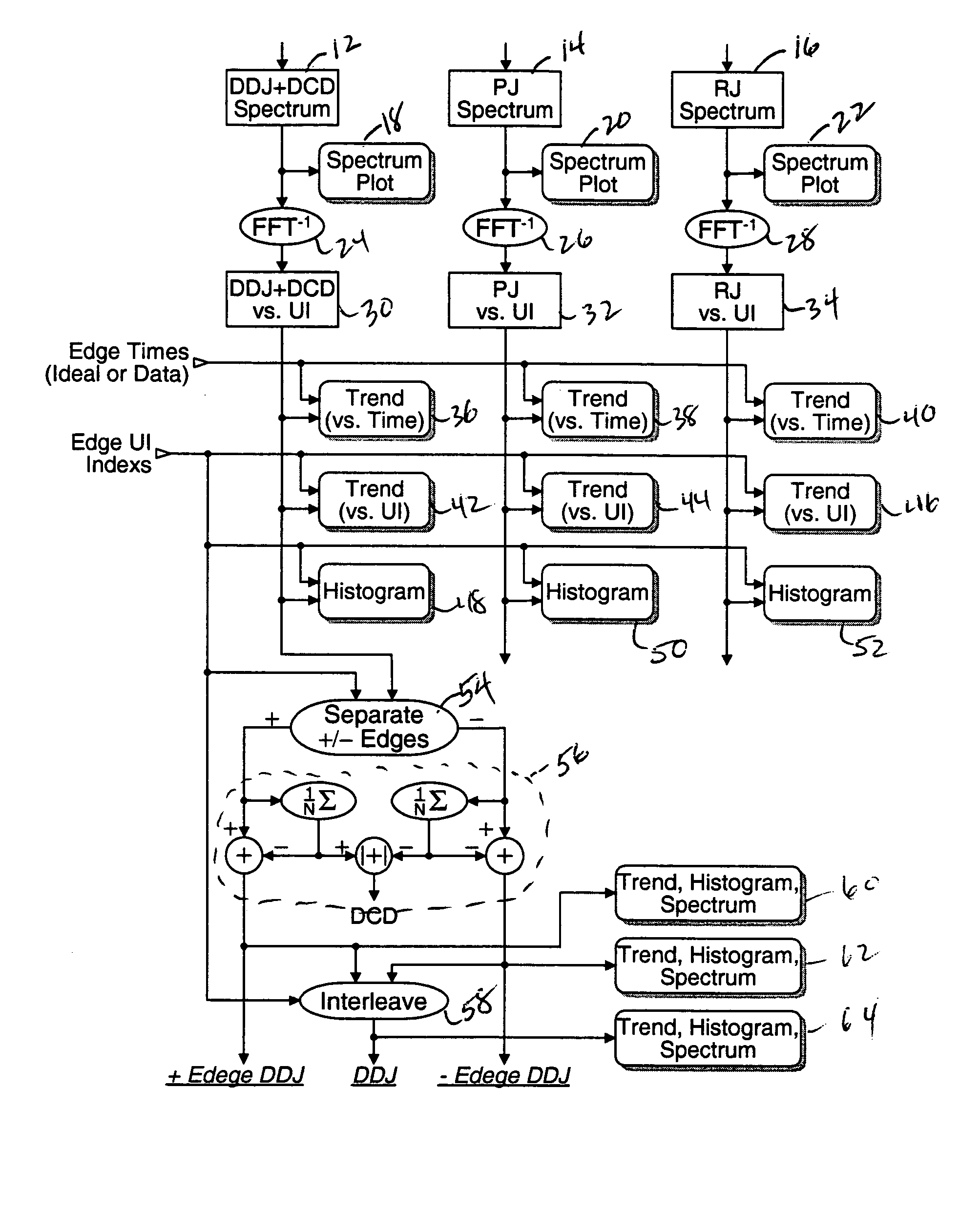
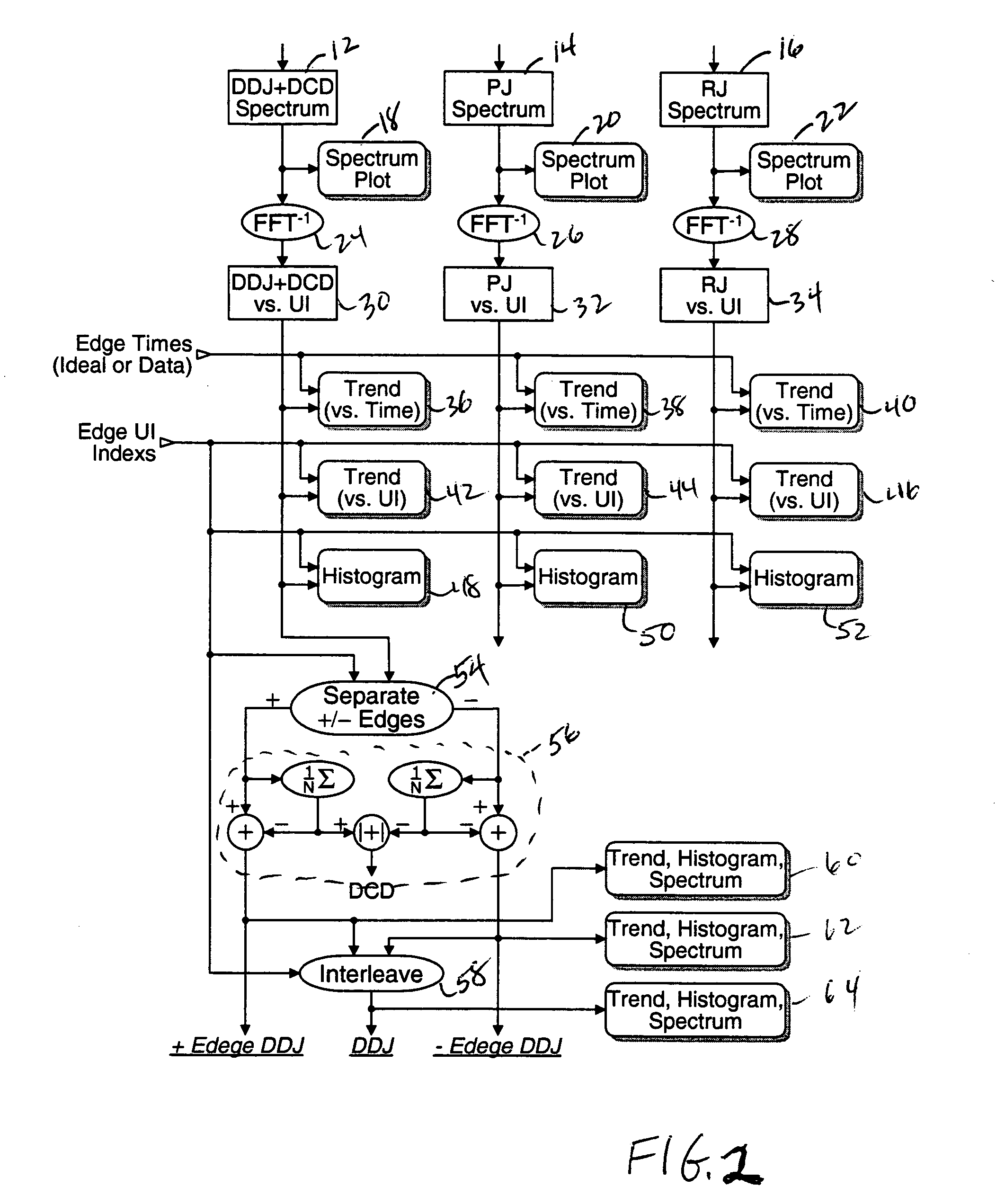
[0018] Referring now to FIG. 2 using the spectrum approach as disclosed in the above-mentioned U.S. Pat. No. 6,832,172 (FIGS. 5 and 8) the jitter is separated spectrally into DDJ+DCD (12), PJ (14) and RJ (16). The prior art as exemplified by the above-mentioned U.S. Pat. No. 6,832,172 (FIG. 6) only provides a spectral display of the total jitter. However the present invention provides a spectral display (18, 20, 22) for each of the three separated jitter components. Each of the spectral components (12, 14, 16) is converted to the time domain by an inverse DFT function (24, 26, 28) to provide jitter versus unit interval data (30, 32, 34). From the jitter versus unit interval data, trend versus time plots (36, 38, 40) using edge times (ideal or measured), trend versus UI plots (42, 44, 46) using edge unit interval indices and histogram plots (48, 50, 52) may be displayed.

[0019] The PJ spectrum plot may be analyzed further to differentiate PJ components so that, by providing a time do...


PUM


Abstract

For a jitter measurement product histograms, trends and spectrums of random and deterministic jitter components are provided on a jitter component basis rather than just on overall jitter. At each stage of the jitter separation histograms, time trends (measurement vs. time), cycle trends (measurement vs. cycle or UI) or spectrums may be provided. Additionally the spectrum for a periodic jitter component may be further separated into sub-spectrums representing correlated sub-sets of the periodic jitter component. Conversion of each sub-spectrum into the time domain provides a characteristic signal that may identify one source of the periodic jitter. From the various plots the contribution of a particular jitter component or a particular combination of jitter components to an eye opening and system performance may be obtained.

Description

BACKGROUND OF THE INVENTION [0001] The present invention relates to data signal timing measurements, and more particularly to histograms, trends and spectrums of random and deterministic jitter. [0002]“Jitter” is a well-known term of art used to define the deviation from an ideal timing of an event in an electrical signal. Jitter in digital signals, if large enough, can render the digital signals unusable as the values of data units within the signal become ambiguous. For example excessive jitter may increase the bit error rate (BER) of a communication signal by causing incorrect decisions on a data bit stream. In digital systems jitter may violate timing margins, causing circuits to behave improperly. As a result accurate jitter measurements are necessary to determine the robustness of a system and how close it is to failing. [0003] Instruments that make jitter measurements in serial data signals, clocks and other signals have been available for many years. More recently there have...

Claims


Application Information

Patent Timeline
IPC IPC(8): H04L1/20H04Q1/20
CPCH04L1/205
Inventor WARD, BENJAMIN A.TAN, KANGUENTHER, MARK L.
Owner WARD BENJAMIN A
Why Eureka
Try Eureka