Image transforming device and method thereof

a technology of image transforming and transforming device, which is applied in the direction of instruments, sun visors, transportation and packaging, etc., can solve the problems of blurring phenomenon, inability to express edge areas distinctively, and very sharp images

Inactive Publication Date: 2005-10-20
S PRINTING SOLUTION CO LTD
View PDF7 Cites 18 Cited by
  • Summary
  • Abstract
  • Description
  • Claims
  • Application Information

AI Technical Summary

Benefits of technology

[0017] It is an aspect of the present invention to provide an image transforming apparatus that can transform an image into a high-resolution i

Problems solved by technology

Since the edge information is changed into the maximum value or the minimum value among adjacent pixels, there is a problem that the expressed image becomes very sharp.
That is, the edge area is expressed having bright and dark areas and this causes a problem in that the edge appears to have two edges.
Therefore, if the wei

Method used


Image

  • Image transforming device and method thereof
  • Image transforming device and method thereof
  • Image transforming device and method thereof

Examples


Embodiment Construction

[0044] Certain embodiments of the present invention will be described in greater detail with reference to the accompanying drawings.

[0045] In the following description, the same drawing reference numerals are used for the same elements throughout the drawings. The matters defined in the description such as a detailed construction and elements are exemplary. Thus, it should be apparent that the present invention can be performed without the examples. Also, well-known functions or constructions are not described in detail since they would obscure the invention in unnecessary detail.

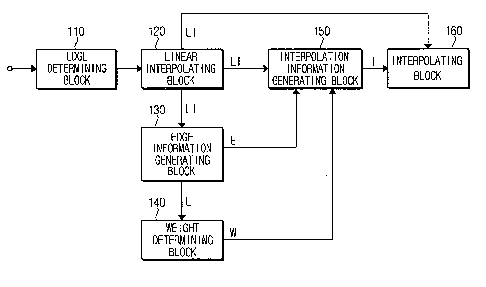
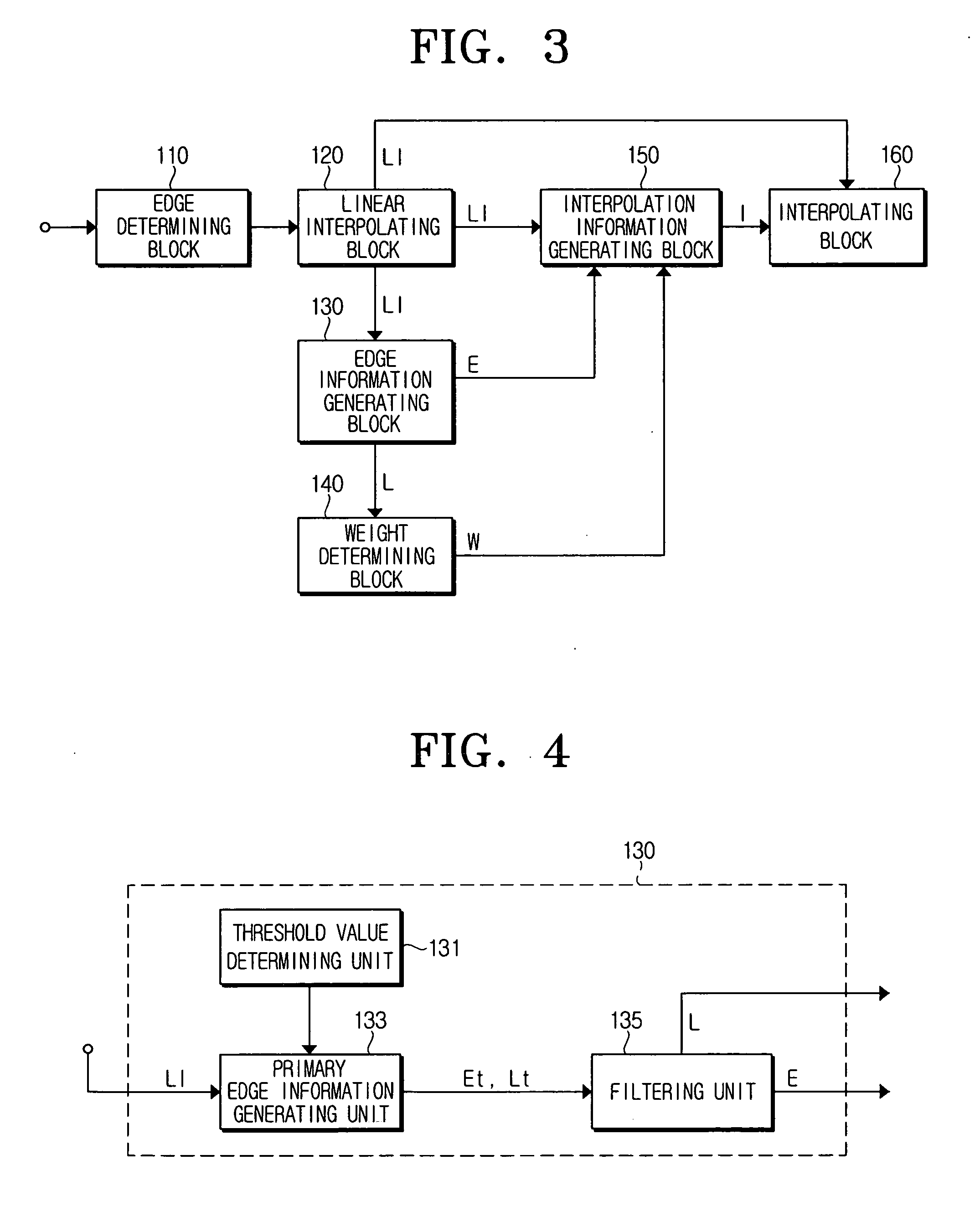
[0046]FIG. 3 is a block diagram of an image transforming apparatus in accordance with an embodiment of the present invention. As shown in FIG. 3, the image transforming apparatus comprises an edge determining block 110, a linear interpolating block 120, an edge information generating block 130, a weight determining block 140, an interpolation information generating block 150, and an interpolating block 16...


PUM


Abstract

An image transforming apparatus and method include a linear interpolation block for generating linear interpolation information for a pixel to be interpolated between original pixels of a predetermined image; an edge information generating block for generating edge information and edge location information; a weight determining block for determining a weight for the linear interpolation information and the edge information of the interpolation pixel based on the edge location information; an interpolation information generating block for determining a pixel value of the interpolation pixel by reflecting the weight to the edge information and the linear interpolation information; and an interpolating block for generating the interpolation pixel based on the pixel value determined in the interpolation information generating block. Therefore, an image can be transformed into a high-resolution enlarged image with an edge area expressed clearly.

Description

CROSS-REFERENCE TO RELATED APPLICATIONS [0001] This application claims the benefit under 35 U.S.C. § 119(a) from Korean Patent Application No. 2004-27030 filed on Apr. 20, 2004 with the Korean Intellectual Property Office, the entire contents of which are incorporated herein by reference. BACKGROUND OF THE INVENTION [0002] 1. Field of the Invention [0003] The present invention relates generally to an image transforming apparatus and a method thereof. More particularly, the present invention relates to an image transforming apparatus that can clearly display an edge area of an image when the image is enlarged or transformed into high-resolution image, and a method thereof. [0004] 2. Description of the Related Art [0005] As electronic technology has been evolving, photographing devices such as digital cameras and mobile phones with a built-in camera have increased in popularity. Digital images photographed by the photographing devices can be magnified or reduced by a user. Also, they ...

Claims


Application Information

Patent Timeline
IPC IPC(8): G06K9/00G06K9/40G06T3/40
CPCG06T3/403B60Q3/252B60Q3/82B60J3/0234
Inventor CHAE, WON-SEOK
Owner S PRINTING SOLUTION CO LTD
Why Eureka
Try Eureka