Device for fixing a rotor on a shaft

a technology for fixing devices and shafts, which is applied in the direction of propellers, propulsive elements, water-acting propulsive elements, etc., can solve the problems of thread fretting, rotor unbalance during operation, and damage to soft materials, so as to achieve simple and very accurate centering, the effect of positive effect on the transmission of torque and torque fluctuations

Inactive Publication Date: 2005-10-20
ABB TURBO SYST
View PDF5 Cites 29 Cited by
  • Summary
  • Abstract
  • Description
  • Claims
  • Application Information

AI Technical Summary

Benefits of technology

[0011] If one or more centering surfaces are provided on the outer circumference of the shaft journal, these centering surfaces interacting in a centering manner with one or more centering surfaces on the inner circumference of the bush, simple and very accurate centering can be achieved. Threads are arranged on the outer circumference of the shaft journal and the inner circumference of the bush axially adjacent to the centering surfaces, these threads interacting in a positive-locking manner and producing a rotationally fixed connection between impeller and shaft. It is advantageous if the axial extent of the thread corresponds approximately to one third to two thirds of the radially inner axial extent of the bush.
[0012] For good seating, the bush has sections having a different inside diameter which are axially one behind the other, decrease toward the impeller and are designed to be diametrically opposed to the shaft journal. If the internal thread of the bush for screwing onto the shaft journal is arranged on a section of a large inside diameter of the bush, this has a positive effect on the transmission of torques and torque fluctuations.

Problems solved by technology

Since the impellers are often produced from a material different from that of the shaft, problems repeatedly occur with these screwed connections on account of different coefficients of expansion of the materials, a factor which may lead to rotor unbalance during operation.
The softer material may also sustain damage during repeated release and tightening in the region of the thread.
Furthermore, “fretting” of the threads may occur.
Thread furrows which are made directly in the hub of the impeller or in the shaft may lead to unfavorable notch effects in the components, a factor which may lead to the fracture of the hub in the case of threads in the hub.
This is a very big problem in turbochargers having ram induction, the impellers of which are subjected to considerable torque fluctuations.
In this design, the blind hole and end face of the hub extension, the bush together with flange, shoulder and thread, and also the shaft journal together with thread and shoulder must be worked very accurately, which is complicated and expensive.
In addition, this design leads to large leakage flows.
Nonetheless, such a connection cannot be used for connections in which very high torques or high torque fluctuations have to be transmitted between impeller and shaft, as is the case, for example, in turbochargers having ram induction, since the torque transmission is inadequate.

Method used


Image

  • Device for fixing a rotor on a shaft
  • Device for fixing a rotor on a shaft
  • Device for fixing a rotor on a shaft

Examples


Embodiment Construction

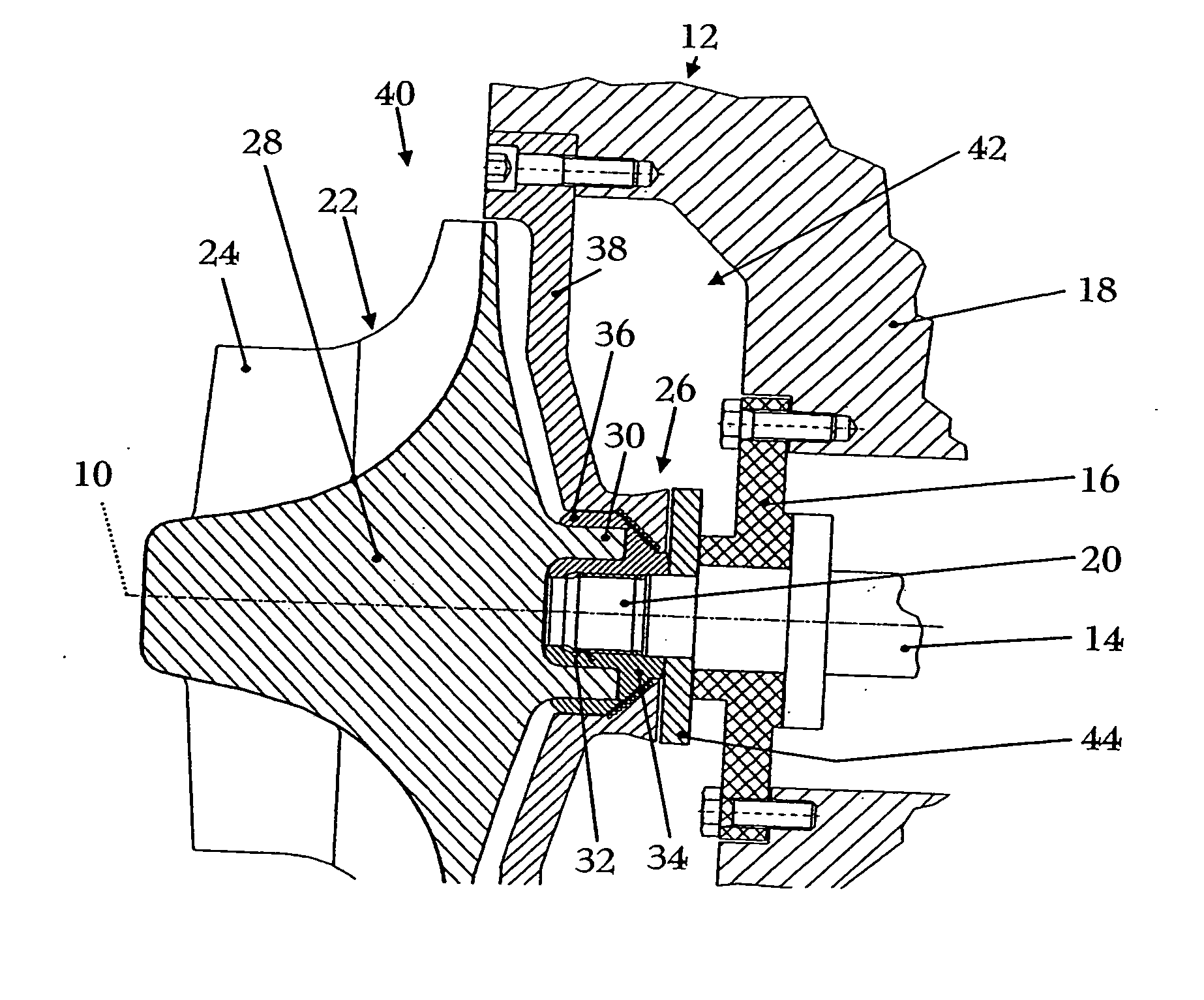
[0006] The object of the invention is therefore to provide a fastening arrangement for an impeller on a shaft, in particular for the impeller of a turbocharger on a turbocharger shaft, which fastening arrangement avoids the abovementioned disadvantages and permits the transmission of even very high torques and / or large torque fluctuations.

[0007] This object is achieved by a fastening arrangement for an impeller on a shaft having the features of patent claim 1.

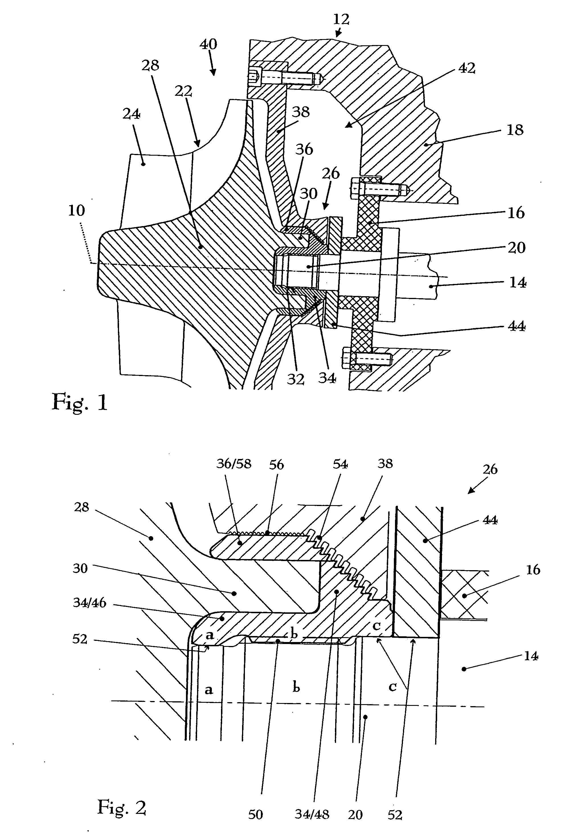
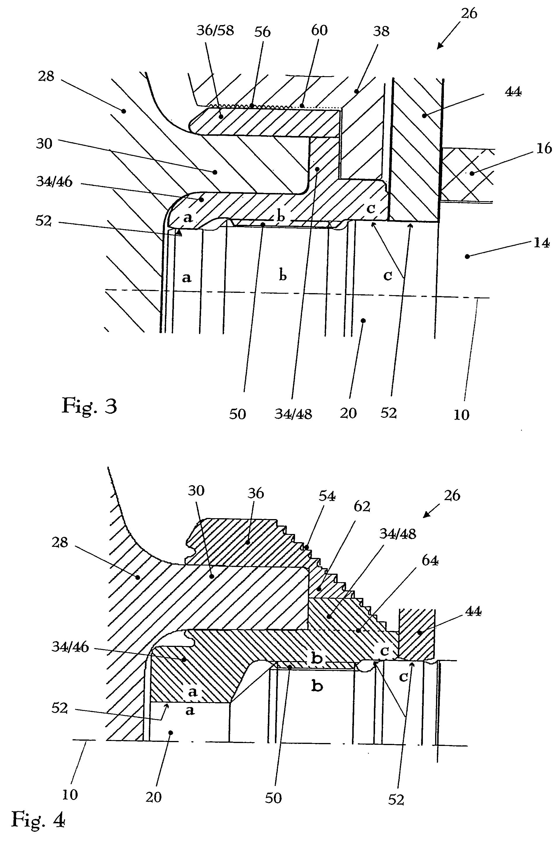
[0008] The fastening arrangement according to the invention, in addition to the abovedescribed, known hub extension with central recess on the shaft side of the impeller and the bush which can be inserted frictionally into the hub extension and can be screwed onto the shaft, also has a press sleeve which can be frictionally connected radially on the outside to the hub extension. For this purpose, the hub extension is designed approximately in the shape of a hollow cylinder at least in the region of its shaft-side end, althoug...


PUM


Abstract

The fastening arrangement (26) for an impeller (22) on a shaft (14), in particular for an impeller (22) of a turbocharger on a turbocharger shaft (14), comprises a bush (34), which can be screwed onto a shaft journal (20) of the shaft (14), and a shaft-side hub extension (30) of the impeller (22) having a central recess (32), into which the bush (34) can be inserted in a frictional manner. The hub extension (30), at least in the region of its shaft-side end, is designed approximately in the form of a hollow cylinder. The fastening arrangement (26) also comprises a press sleeve (36) which can be frictionally connected radially on the outside to the hub extension (30).

Description

TECHNICAL FIELD [0001] The invention relates to a fastening arrangement for an impeller on a shaft, in particular for an impeller of a turbocharger on a turbocharger shaft, according to the preamble of patent claim 1. PRIOR ART [0002] In high-speed machines, such as, for example, in high-speed fluid-flow machines, the connection between the impellers and the shaft must satisfy stringent requirements. These connections must be absolutely rotationally fixed at high speeds, despite the high forces which occur, they must be able to transmit high torques and have a long service life, but must nonetheless often be releasable for maintenance purposes. [0003] Various possible ways of realizing such connections have been proposed. Thus, the impeller, for example, may be provided with a continuous central bore and the shaft may be provided with a tapped hole, so that the impeller can then be screwed on with a clamping screw. Or the impeller, on its side facing the shaft, is provided with a bl...

Claims


Application Information

Patent Timeline
Patent Type & Authority Applications(United States)
IPC IPC(8): F01D5/04F01D1/00F01D5/02F01D11/02F01D25/16F02B39/00F04D29/26F16D1/06F16D1/08
CPCF01D5/025F04D29/266F05D2220/40F16D1/0852F16D2001/062F16D1/0835F01D5/02F16D1/08
Inventor THIELE, MARTINKUHNEL, JANPETERBATTIG, JOSEF
Owner ABB TURBO SYST
Why Eureka
Try Eureka