Conical piston solids discharge centrifugal separator

a centrifugal separator and piston technology, applied in centrifuges, filtration separation, separation processes, etc., can solve the problems of damage to sensitive materials such as biological substances that include intact cells, poor yield, and especially problematic for high-value materials

Active Publication Date: 2005-10-20
CARR ROBERT BRET
View PDF31 Cites 23 Cited by
  • Summary
  • Abstract
  • Description
  • Claims
  • Application Information

AI Technical Summary

Benefits of technology

[0008] In accordance with the present invention, a centrifugal separator is disclosed that performs well with sticky solids and that exhibits low-shear acceleration of feed liquid, making the separator particularly useful for sensitive materials such as pharmaceutical and biological materials.
[0010] The separator further includes a piston assembly including a conical piston coupled to a piston actuator, with the piston being disposed within the bowl in tight-fitting relationship with the inner surface thereof. In a solids discharge mode of operation, the piston actuator urges the piston axially downward to force the accumulated solids from the bowl via the opening in the conical lower end of the bowl. The conical shape promotes relatively complete discharge of the solids.
[0012] The disclosed separator also includes a two-part piston shaft having a connected position and a disconnected position. When the piston shaft is in the disconnected position, the piston is permitted to be forced upwardly and to rotate with the bowl. When the piston shaft is in the connected position, the piston can be pushed and pulled axially by the piston actuator, thus facilitating the solids discharge mode of operation.

Problems solved by technology

For example, many separators may not be capable of completely discharging residual solids that are sticky, which can result in poor yield.
This can be especially problematic for high-value materials such as are encountered in pharmaceutical processes.
Additionally, many separators subject the feed material to very high shear forces when accelerating the feed liquid to the rotational speed of the bowl, which can damage sensitive materials such as biological substances that include intact cells.

Method used


Image

  • Conical piston solids discharge centrifugal separator
  • Conical piston solids discharge centrifugal separator
  • Conical piston solids discharge centrifugal separator

Examples


Embodiment Construction

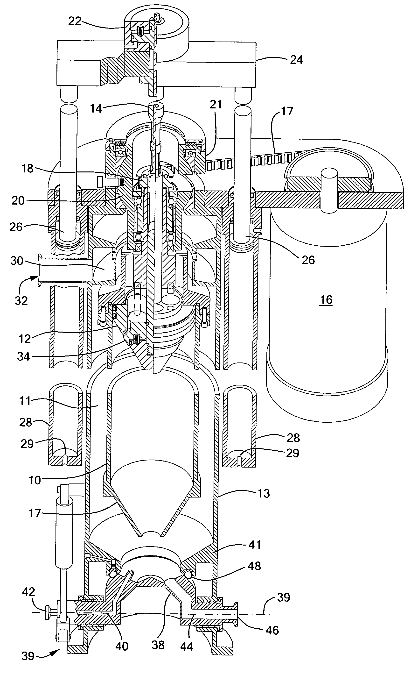
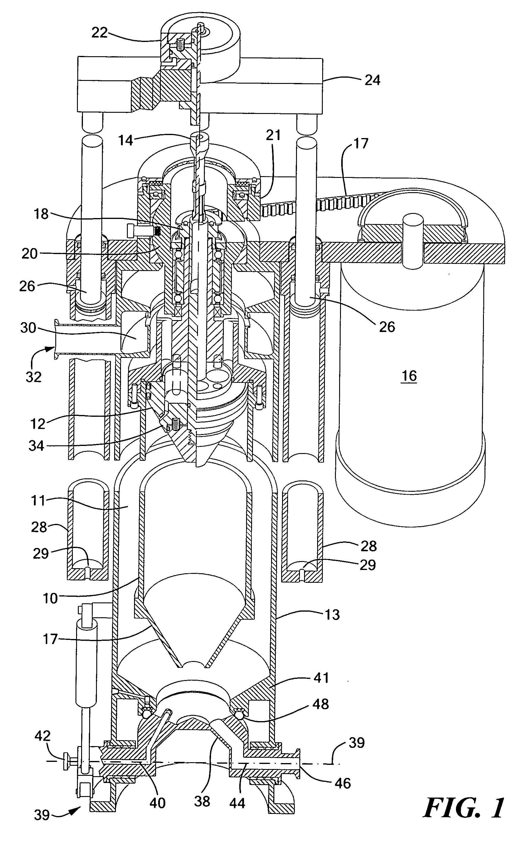
[0020]FIG. 1 shows a centrifugal separator in vertical section, with a middle portion removed so as to illustrate a horizontal section as well. The centrifugal separator includes a cylindrical separator bowl 10 mounted in a central region 11 of a separator housing 13. The separator bowl 10 is preferably a cylindrical type bowl having a relatively small diameter D and a length L such that the ratio of L / D is approximately 5 / 1 or greater. The separator includes a piston assembly consisting of a piston 12 connected to a piston shaft 14. As shown, the piston 12 has a conical shape that matches the shape of a conical feed cone 17 of the bowl 10. The feed cone 17 acts as a rotational accelerator of the feed liquid during a feed mode of operation of the separator.

[0021] A variable speed drive motor 16 is connected by a drive belt 17 to a drive pulley 18 of a spherically mounted bearing and spindle assembly 20 located at a collar-like extension 21 of the upper end of the separator housing ...


PUM

PropertyMeasurementUnit
speedaaaaaaaaaa
hydraulic pressureaaaaaaaaaa
flexibleaaaaaaaaaa

Abstract

A centrifugal separator includes a cylindrical bowl having a conical lower end with an opening through which feed liquid is injected during a feed mode of operation. The feed liquid is separated into centrate and solids, which accumulate along the inner surface of the bowl. A piston assembly includes a conical piston coupled to a piston actuator by a two-part piston shaft. During the feed mode of operation, the piston shaft is disconnected, the piston is held in an uppermost position by hydraulic pressure from the feed liquid, and a centrate valve on the piston is urged open to permit the centrate to flow out to a centrate discharge port. In a solids discharge mode of operation, the piston shaft is connected and the piston actuator urges the piston axially downward, closing the centrate valve and forcing the accumulated solids from the bowl via the opening in the conical lower end of the bowl.

Description

CROSS REFERENCE TO RELATED APPLICATIONS [0001]——None——STATEMENT REGARDING FEDERALLY SPONSORED RESEARCH OR DEVELOPMENT [0002]——Not Applicable——BACKGROUND OF THE INVENTION [0003] The present invention generally relates to centrifuges and in particular to centrifuges enabling automatic discharge of solids that accumulate during separation. [0004] Many different types of centrifugal separators are known for separating heterogeneous mixtures into components based on specific gravity. A heterogeneous mixture, which may also be referred to as feed material or feed liquid, is injected into a rotating bowl of the separator. The bowl rotates at high speeds and forces particles of the mixture, having a higher specific gravity, to separate from the liquid by sedimentation. As a result, a dense solids cake compresses tightly against the surface of the bowl, and the clarified liquid, or “centrate”, forms radially inward from the solids cake. The bowl may rotate at speeds sufficient to produce for...

Claims


Application Information

Patent Timeline
Patent Type & Authority Applications(United States)
IPC IPC(8): B04B11/05B04B11/06B04B11/08
CPCB04B11/05B04B2005/0485B04B11/06
Inventor CARR, ROBERT B.
Owner CARR ROBERT BRET
Why Eureka
Try Eureka