Multi-functional joint brace

a multi-functional, joint brace technology, applied in the field of joint support devices, can solve the problems of increasing the time and expense required to fully heal a damaged joint, increasing the cost and inconvenience of repairing and rehabilitating a joint, and preventing so as to facilitate switching, provide stability to the wearer, and prevent wearer discomfort or injury.

Inactive Publication Date: 2007-01-02
DJO
View PDF20 Cites 25 Cited by
  • Summary
  • Abstract
  • Description
  • Claims
  • Application Information

AI Technical Summary

Benefits of technology

[0012]The present invention overcomes the disadvantages in the prior art by providing a lightweight and streamlined joint brace device that can perform different rehabilitative functions. The joint brace disclosed herein achieves advancements over the prior art because of its unique design. The joint brace contains sturdy uprights that provide stability to the wearer. In a preferred embodiment, straps containing air-cells securely hold the brace in position on the user's body, while distributing pressure evenly over the area of the air-cell to prevent wearer discomfort or injury.
[0013]The joint brace described herein comprises a hinged movement arm, a means for allowing controlled free movement through the movement arm hinge about a predetermined range of motion, a hinged drive arm, a means for releasably locking said drive arm hinge at a predetermined angle, and adjustable means for connecting said movement arm to said drive arm such that the hinges thereof are in alignment. The means for allowing controlled free movement through the movement arm hinge can comprise a range of motion assembly associated with the movement arm hinge. The means for releasably locking the drive arm can comprise a novel locking mechanism associated with the drive arm hinge that can be used to immobilize a joint by locking the brace into a fixed position. The novel locking mechanism can be switched easily from a locked to an unlocked position, without any time-consuming procedures involving insertion and / or removal of pins into the brace. In the locked position, the brace can statically stretch the joint in either flexion or extension. The brace comprises an angle-adjustment means that can be adjusted so that the brace achieves the desired angle of flexion or extension. The angle-adjustment mechanism can comprise a detailed scale so that the degree of extension and flexion can be closely monitored. The static stretch feature provides the benefits of stability and protection while preparing the joint for eventual movement.
[0014]An advantage of the novel design of the brace is that the locking mechanism can be disengaged while the brace is positioned on a wearer to provide the wearer with free movement of the joint within the natural axis of movement while preventing the joint from moving in a direction outside of the joint's natural axis of movement. The range of motion assembly can be adjusted to set the maximum and minimum angle through which the joint can move in flexion and / or extension. Limiting the maximum and minimum angle of motion ensures that the wearer does not exceed predetermined limits, which could injure the joint. The brace advantageously performs the multiple functions of protection, immobilization, static stretching, and controlled free movement of a joint.
[0015]The brace can be adjusted easily to fit either the right or left side of a wearer's body, and to fit a wearer of small or large body size. Further, the novel locking mechanism contains no bulky motors or heavy springs, and in a preferred embodiment the adjustment knob of the locking mechanism easily can be removed and reattached as needed for the comfort of the wearer.
[0016]The brace also comprises an override means that prevents damage to the locking mechanism when the brace is subjected to a large external force.

Problems solved by technology

The expense and inconvenience of repairing and rehabilitating a joint is increased if more than one brace must be used during the healing process.
The use of different braces throughout the rehabilitation process can be inconvenient for both the health-care provider and the patient, and can increase the time and expense required to fully heal a damaged joint.
Currently available joint support devices do not combine different rehabilitative features into one device.
Many of the currently available joint support devices do not interchange easily between joints on the left and right sides of the body, and do not interchange easily between persons of different sizes.

Method used


Image

  • Multi-functional joint brace
  • Multi-functional joint brace
  • Multi-functional joint brace

Examples


Embodiment Construction

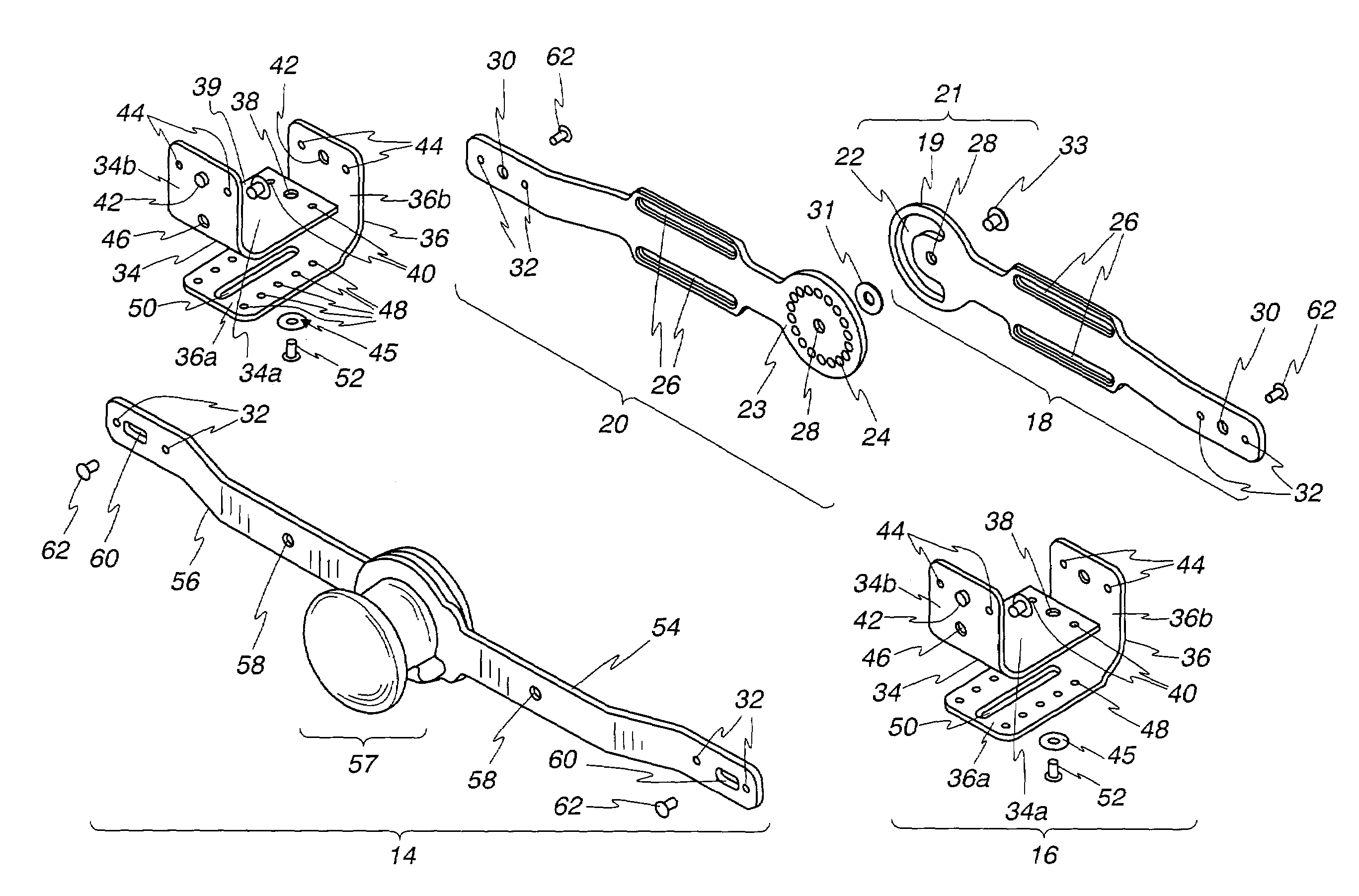
[0037]The following detailed description is of an embodiment of the invention wherein the multi-functional brace is adapted for use with an elbow. It is to be understood, however, that the invention is not so limited. For example, those skilled in the art will understand how to adapt the principles of the invention as disclosed herein to create a multi-functional brace for use with a knee or any other joint.

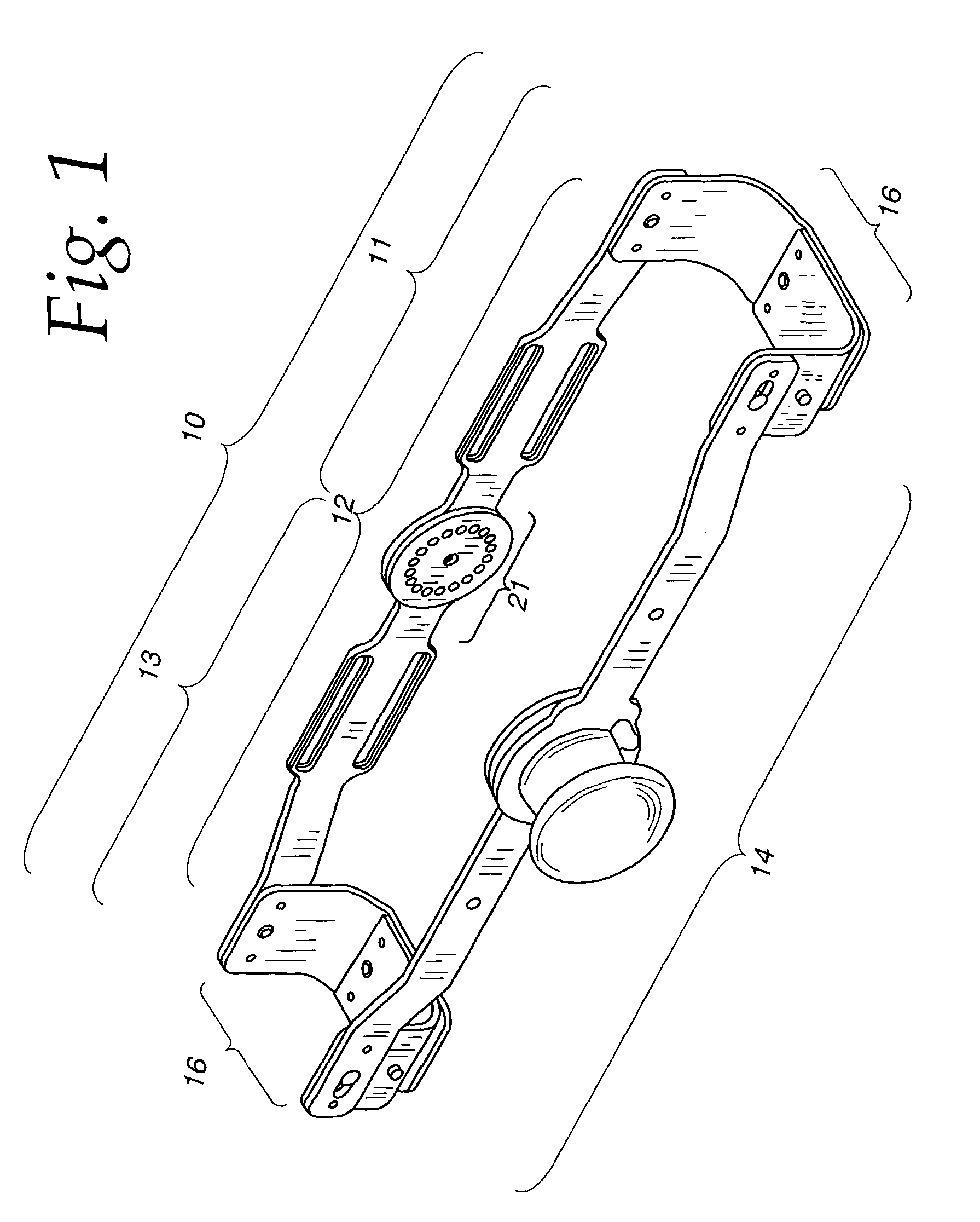
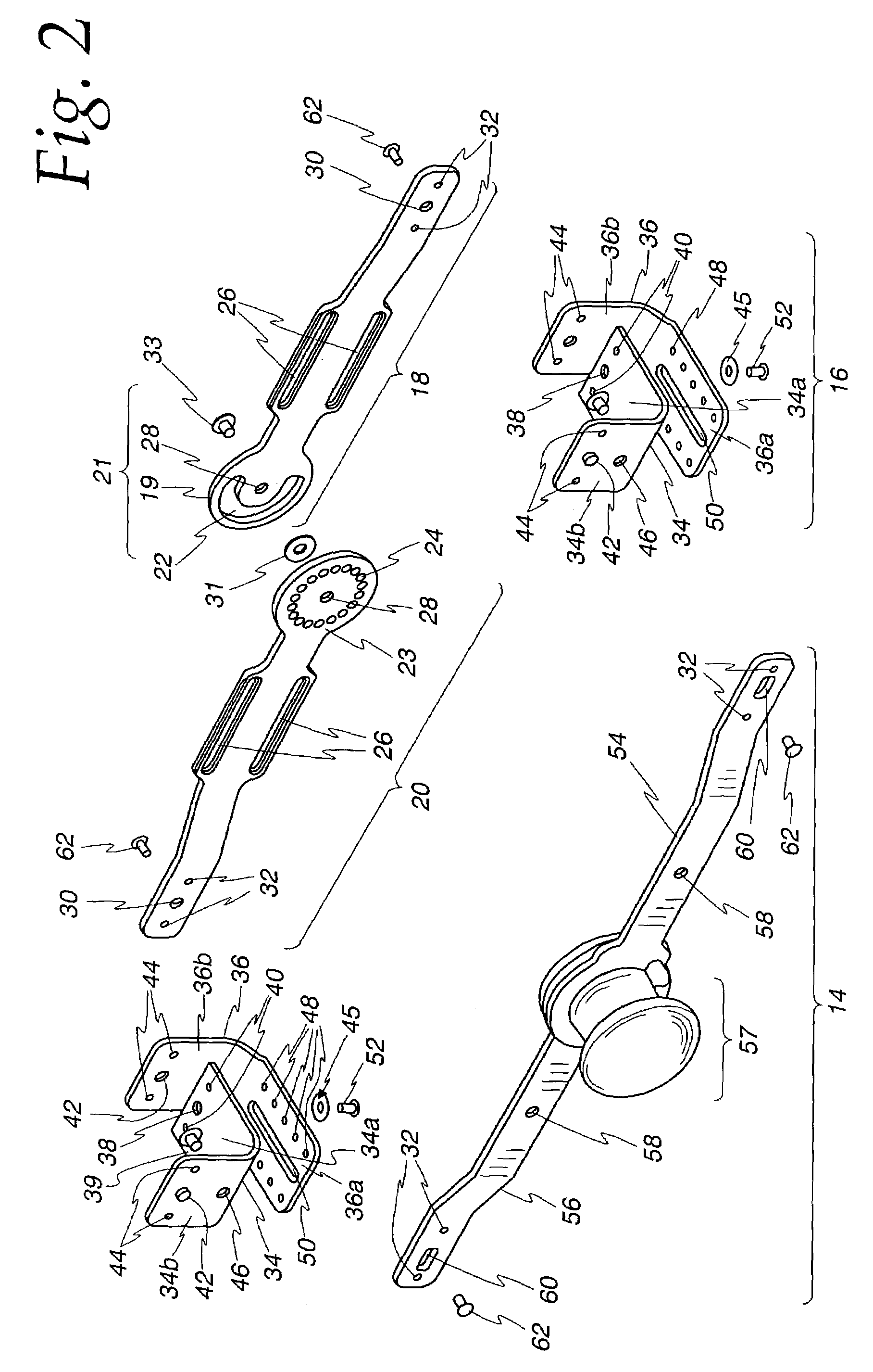
[0038]Reference is now made to the figures wherein like parts are referred to by like numerals throughout. With particular reference to FIG. 1, a multi-functional elbow brace 10 according to the present invention comprises a hinged movement arm 12 and a hinged drive arm 14. Adjustable means for connecting hinged movement arm 12 and hinged drive arm 14 comprise adjustable cross brackets 16. Brace 10 comprises a proximal portion 11 and a distal portion 13. In some embodiments, the proximal portions of hinged movement arm 12 and hinged drive arm 14 can be wider than the distal porti...


PUM


Abstract

A multi-functional brace for a joint includes a releasable locking mechanism that allows the brace to be set for static stretch of the joint in either flexion or extension, and a range of motion assembly that allows for free movement of the joint through its natural axis over a controlled range of motion when the locking mechanism is released.

Description

BACKGROUND OF THE INVENTION[0001]1. The Field of the Invention[0002]The present invention relates generally to joint support devices, and in particular, to a multi-functional joint brace that protects the joint from internal and external forces and provides for immobilization, static stretching of the joint alternately in flexion and extension, and free movement of the joint over a controlled range of motion.[0003]2. Description of the Related Art[0004]In the health care field, joint support devices are used to protect and promote healing of damaged joints. A wide variety of externally applied supports and braces are known and used in the field. One variety of devices protects joints by immobilization. These devices also can protect the joint by providing a rigid surface that deflects the energy from an external force. A traditional plaster cast is a joint support device that protects by immobilization and by providing a rigid shell.[0005]Another variety of devices promotes healing ...

Claims


Application Information

Patent Timeline
Patent Type & Authority Patents(United States)
IPC IPC(8): A61F5/00A61F5/01
CPCA61F5/0125A61F2005/0139A61F2005/0179A61F2005/0167A61F2005/0158
Inventor SALMON, SCOTTUEDA, DANJOACHIM, ROBERTTURCHI, MARIOHARGRAVE, DAVID C.MORREY, BERNARDO'DRISCOLL, SHAWNADAMS, ROBERT
Owner DJO
Why Eureka
Try Eureka