Minimally invasive pedicle screw access system and associated method

Active Publication Date: 2008-05-15
ZIMMER BIOMET SPINE INC
View PDF29 Cites 139 Cited by
  • Summary
  • Abstract
  • Description
  • Claims
  • Application Information

AI Technical Summary

Benefits of technology

[0008]According to various embodiments of this invention, pedicle screws are inserted into the target vertebrae of a patient's spinal column. The pedicle screw may be cannulated for proper positioning and installation. In one aspect, this invention provides an access system which involves a pedicle screw with incorporated extended tabs that form a single solid pedicle screw assembly The surgical procedure associated with this invention involves making small, discrete incisions for the placement of select pedicle screws. The extended tabs of the pedicle screws retract soft tissue, muscle and the like to thereby provide visibility and access to the head of the pedicle screw. Through the extended tabs, instrumentation such as a spine rod, set screw and other required hardware may be delivered to the pedicle screws.
[0009]In another aspect of this invention, a collar may be coupled around the extended tabs to provide stability to the construct and a platform for additional components of this invention.
[0010]Once the rod is secured with the set screws, a frangible joint joining the tabs to the pedicle screw assembly is broken off using appropriate instrumentation and the extended tabs may be removed. The extended length of the tabs for each pedicle screw extend beyond the surface of the skin (i.e., percutaneously) thereby retracting soft tissue and muscle enabling the surgeon to install the spinal fixation construct with smaller discrete incisions as opposed to an extended incision. As such, a more minimally invasive surgical procedure can be accomplished with this invention thereby allowing for visualization of the

Problems solved by technology

A variety of types of spinal column disorders may be caused by abnormalities, disease, trauma or the like and result in debilitating pain as well as diminished nerve function in many cases.
Visualization of the accuracy of the alignment of the spine rod and the screw heads may be difficult because of visual interference from tissue and blood in the surgical field.
Bending of the spine rod is performed once the screws are placed into the vertebrae and, therefore, visualization of the accuracy of the placement and configuration

Method used


Image

  • Minimally invasive pedicle screw access system and associated method
  • Minimally invasive pedicle screw access system and associated method
  • Minimally invasive pedicle screw access system and associated method

Examples


Example

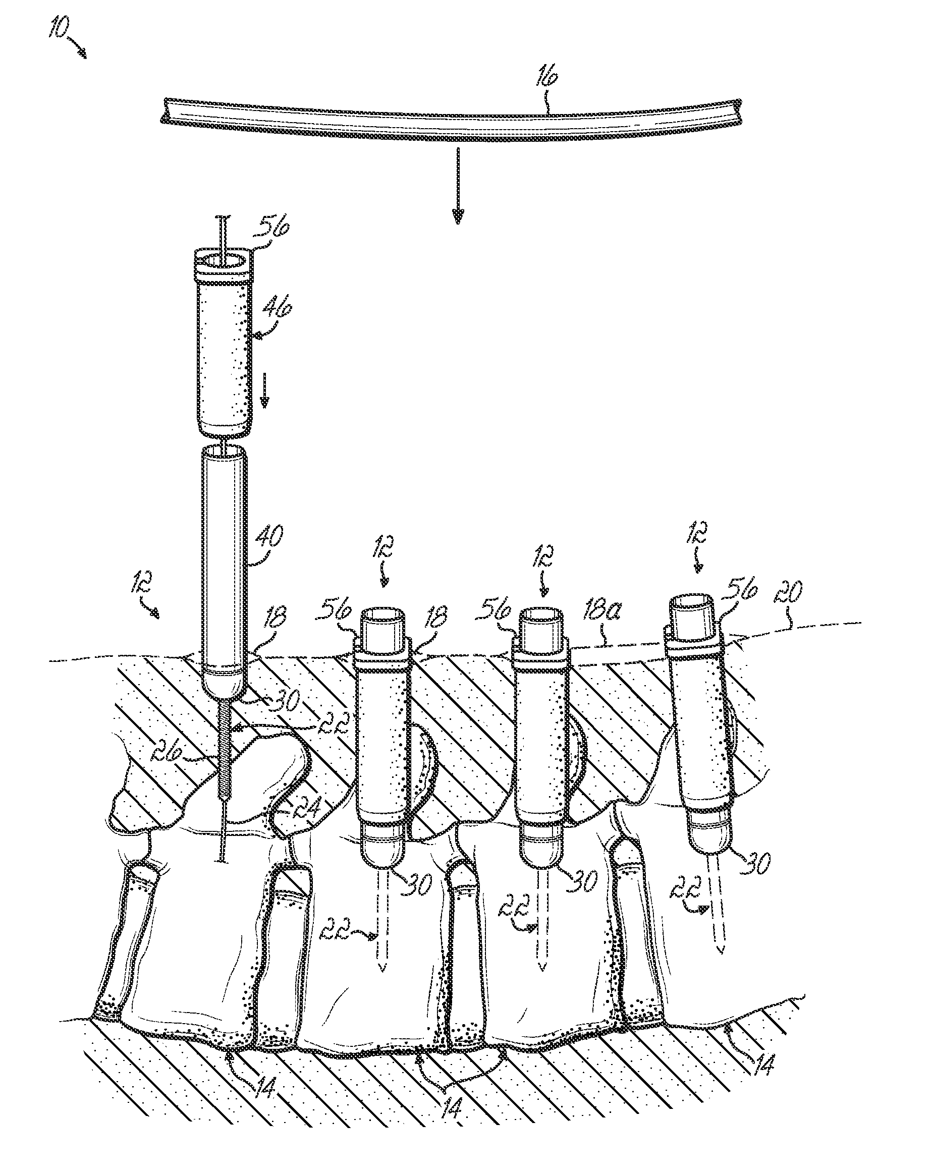
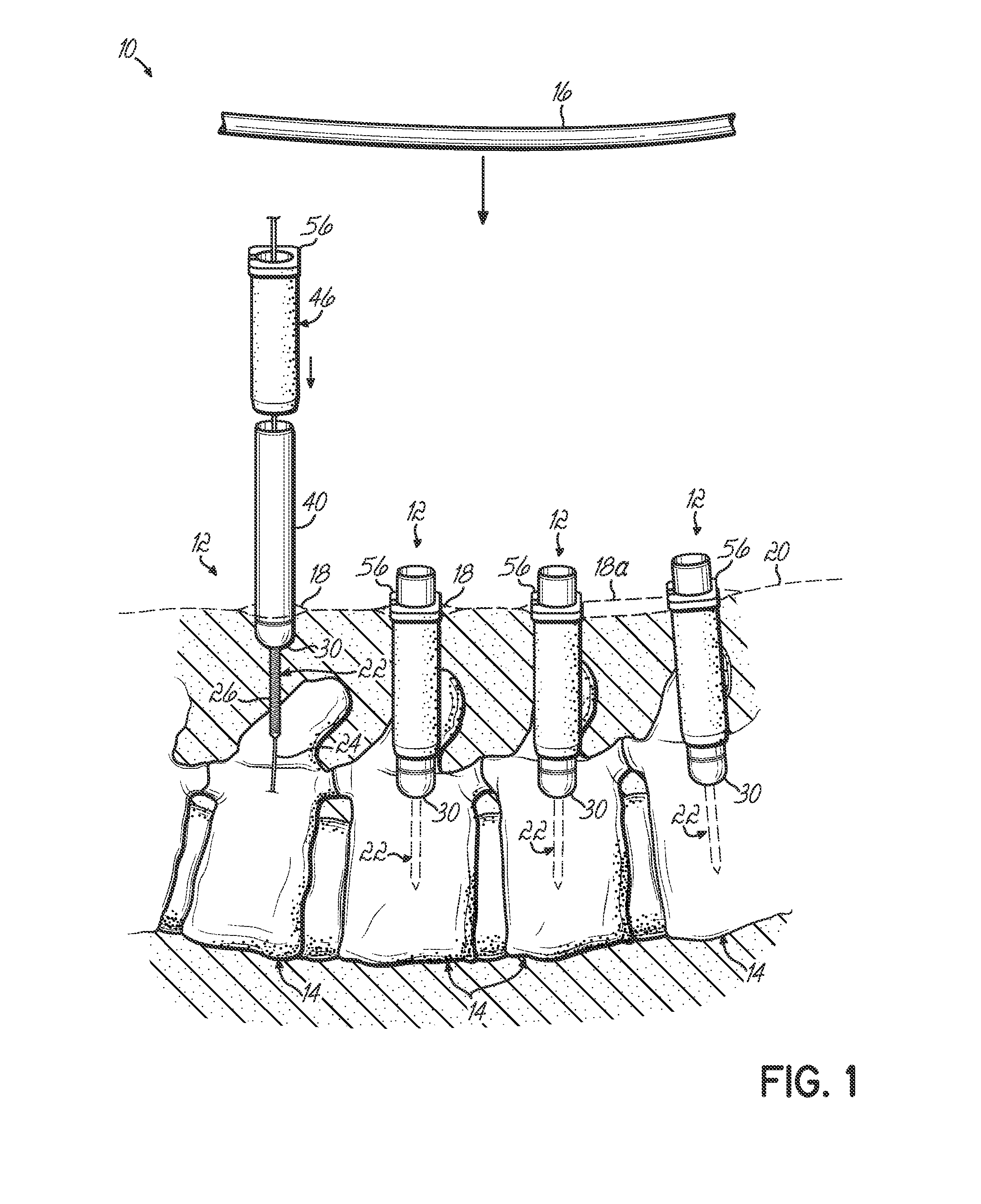
[0020]Referring to FIG. 1, various embodiments of a minimally invasive spinal fixation construct 10 and associated installation method are shown. The spinal fixation construct 10 includes a number of pedicle screw assemblies 12, each of which is inserted into selected vertebrae 14 of a patient. The pedicle screw assemblies 12 are joined together in the spinal fixation construct by a spine rod 16. According to various aspects of this invention, the individual pedicle screw assemblies 12 may be inserted into the patient through discrete and often individual incisions 18 in the patient's skin 20. In certain instances, a single incision 18a may be available to provide installation of multiple pedicle screw assemblies 12 in adjacent vertebrae 14 as shown in FIGS. 1 and 2. The small, discrete incisions 18 provide the opportunity for insertion of a cannulated pedicle screw 22 via a K-wire 24 inserted through the incision 18 to the precise location on the vertebrae 14 for proper installatio...


PUM


Abstract

A spinal fixation access system includes a pedicle screw with extended tabs that form a single solid pedicle screw assembly. The surgical procedure associated with this invention involves making small, discrete incisions for the placement of select pedicle screws. The extended tabs of the pedicle screws retract soft tissue, muscle and the like to thereby provide visibility and access to the head of the pedicle screw. Through the extended tabs, instrumentation such as a spine rod, set screw and other required hardware may be delivered to the pedicle screws. A collar may be coupled around the extended tabs to provide stability to the construct and a platform for additional components of this invention. Once a spine rod is secured to the pedicle screws, a frangible joint joining the tabs to the pedicle screw assembly is broken off using appropriate instrumentation and the extended tabs may be removed.

Description

BACKGROUND[0001]This invention relates generally to spinal fixation devices and more specifically relates to a system and associated method for minimally invasive installation of pedicle screws and spinal rods of spinal fixation constructs.[0002]The human spinal column is a highly complex system of bones and connected tissues that provide support for the body and protects the delicate spinal cord and nerves. The spinal column includes a series of vertebrae stacked one atop the other. Each vertebral body includes a relatively strong cortical bone portion forming the outside surface of the body and a relatively weak cancellous bone portion forming the center of the body. An inter-vertebral disc is situated between each vertebral body that provides for cushioning and dampening of compressive forces applied to the spinal column. The vertebral canal containing delicate spinal cords and nerves is located just posterior to the vertebral bodies.[0003]A variety of types of spinal column diso...

Claims


Application Information

Patent Timeline
IPC IPC(8): A61B17/56A61B17/58
CPCA61B17/7032A61B2019/307A61B17/7037A61B17/7086A61B2090/037
Inventor KUESTER, W. MATTHEWHESTAD, HUGH D.AFERZON, JOSEPHHICKEY, PAUL
Owner ZIMMER BIOMET SPINE INC
Why Eureka
Try Eureka