Flexible member with variable flexibility for providing dynamic stability to a spine

a flexible member and dynamic technology, applied in the field of spine support devices, can solve the problems of inability to allow flexibility variability, inability to manufacture multi-material flexible members, and the cost of additional materials, and achieve the effect of providing dynamic stability to a person's spine and flexibility

Inactive Publication Date: 2009-04-16
ZIMMER SPINE INC
View PDF45 Cites 135 Cited by
  • Summary
  • Abstract
  • Description
  • Claims
  • Application Information

AI Technical Summary

Benefits of technology

[0006]The present invention provides a flexible member having variable flexibility for use with a dynamic stabilization system to provide dynamic stability to a person's spine.
[0010]These and other various configurations of the flexible member can allow for a desired bending of the flexible member, such as easier bending in one direction relative to another, as compared to conventional or typical flexible members which have equal bending force in all directions.
[0012]By virtue of the foregoing, there is provided a flexible member having variable flexibility attributable to a specified configuration for use with dynamic stabilization systems to provide dynamic stability to a person's spine.

Problems solved by technology

While current dynamic stabilization systems include flexible members, these flexible members typically are of a uniform cylindrical shape, which may not allow for variability in flexibility, except by varying the length of the flexible member between pedicle screws.
However, the processes for manufacturing the multi-material flexible members and the additional material itself can be cost prohibitive.
In addition, while some single material flexible members are known to provide variations from the typical cylindrical configuration, e.g., a spiral-patterned flexible member, additional configurations, such as non-uniform or atypical configurations, are needed for providing flexible members with other desirable bending movements.

Method used


Image

  • Flexible member with variable flexibility for providing dynamic stability to a spine
  • Flexible member with variable flexibility for providing dynamic stability to a spine
  • Flexible member with variable flexibility for providing dynamic stability to a spine

Examples


Embodiment Construction

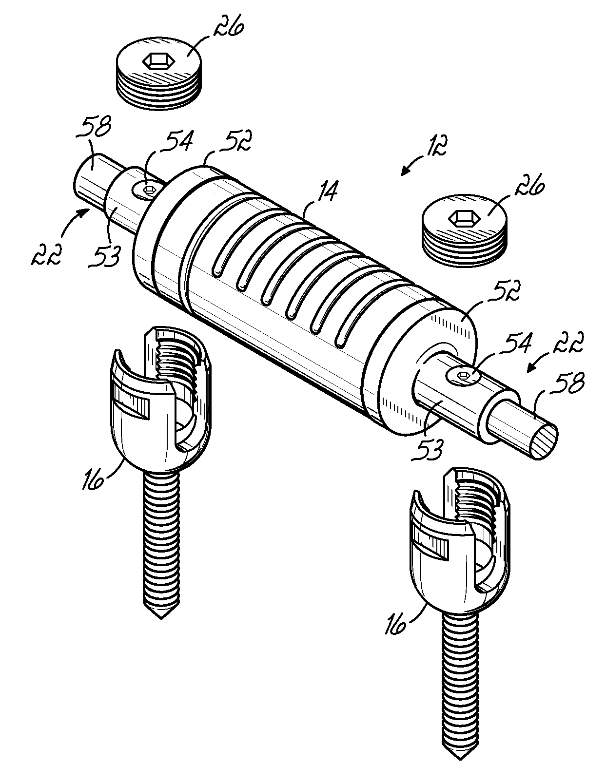
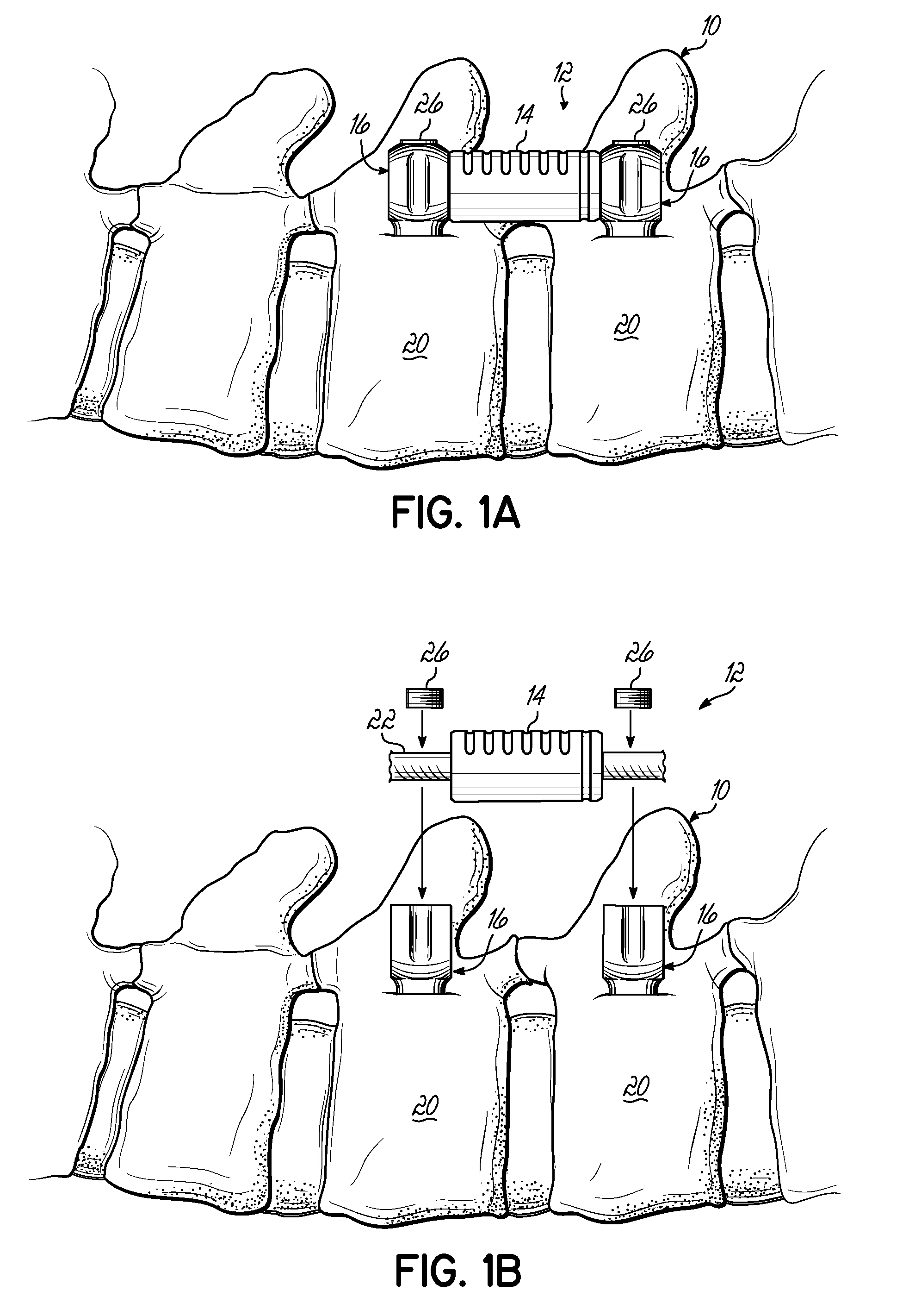
[0030]FIGS. 1A and 1B illustrate cut-away sections of a spine 10 having a dynamic stabilization system or implant 12 implanted therein. The systems 12 of FIGS. 1A and 1B, include a flexible member 14 having variable flexibility positioned between anchor members 16, for example, pedicle screws, installed in adjacent vertebrae 20 of the spine 10.

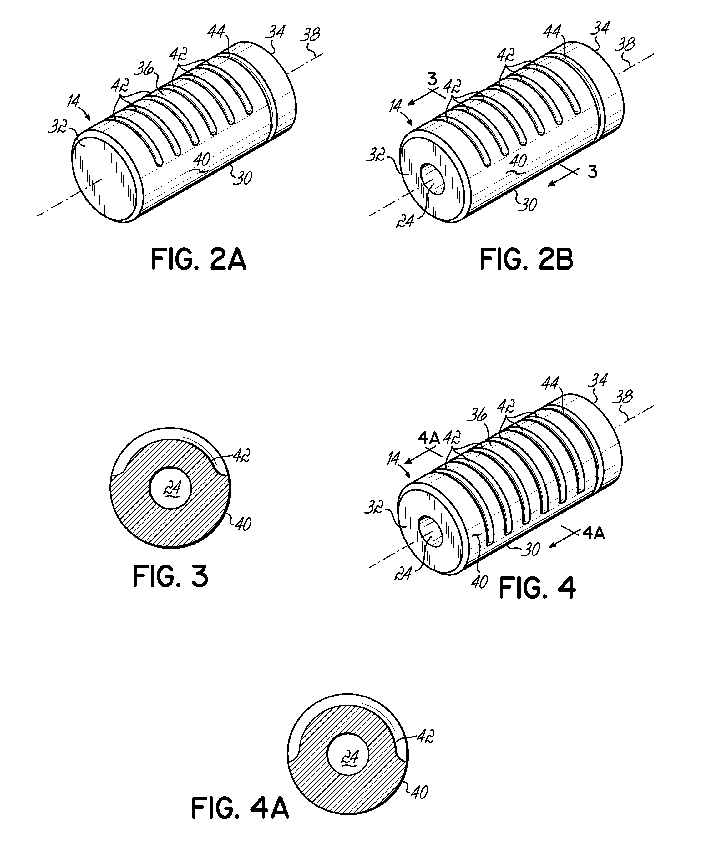
[0031]The anchor members 16 of FIGS. 1A and 1B generally illustrate top loading pedicle screws that retain the flexible members 14 therebetween by means well known in the art. One such top loading type screw is disclosed in U.S. Patent Application Publication No. 2002 / 0035366 to Walder et al., titled “Pedicle Screw For Intervertebral Support Elements”, which is expressly incorporated by reference herein in its entirety. With further reference to FIG. 1B, a connecting member 22 may be passed through an aperture 24 (FIG. 2B) in the flexible member 14, such connecting member 22 then being top loaded and secured within a top portion of each anchor...


PUM


Abstract

The present invention relates to spinal support devices and, more specifically, to a flexible member having variable flexibility attributable to a specified configuration for use with a dynamic stabilization system or implant to provide dynamic stability to a person's spine. The flexible member generally includes a body having a lengthwise axis, an outer surface, and opposing first and second ends with an intermediate portion extending therebetween. The outer surface has one or more grooves providing the flexible member with a variable flexibility. The one or more grooves may be situated generally perpendicular to the lengthwise axis of the body and extending around less than the outer surface of the body, and / or situated generally perpendicular to the lengthwise axis of the body and extending around the outer surface of the body substantially directly in-between the ends.

Description

FIELD OF THE INVENTION [0001]The present invention relates generally to spinal support devices and, more specifically, to a flexible member having variable flexibility for use with a dynamic stabilization system to provide dynamic stability to a person's spine.BACKGROUND OF THE INVENTION [0002]The treatment of acute and chronic spinal instabilities or deformities of the thoracic, lumbar, and sacral spine has traditionally involved the implantation of rigid rods to secure the vertebrae of a patient. More recently, flexible materials have been utilized in connection with anchor members, e.g., pedicle screws, to provide a dynamic stabilization of the spinal column. Such dynamic stabilization systems or implants typically include a flexible member positioned between pedicle screws installed in adjacent vertebrae of a person's spine.[0003]Certain dynamic stabilization systems permit the top loading of a flexible member and connecting member between pedicle screws. One such top loading sy...

Claims


Application Information

Patent Timeline
Patent Type & Authority Applications(United States)
IPC IPC(8): A61B17/70A61B17/58A61B17/04
CPCA61B17/7004A61B17/7008A61B17/7037A61B17/7026A61B17/7032A61B17/701
Inventor HESTAD, HUGH D.OTTE, JOHN F.HILLYARD, ANGELA L.BOSCHERT, PAUL F.RICE, MARK W. DARSTLANCIAL, MIKE E.
Owner ZIMMER SPINE INC
Why Eureka
Try Eureka