Utility or meter pole top reinforcement method and apparatus

a technology of utility or meter poles and reinforcement methods, applied in the field of upstanding pole repair, can solve the problems of many pressure-treated poles, low inventiveness, and the current cost of replacing a utility pole that has lost its structural integrity of about three thousand dollars per pole, and achieve the effect of prolonging the life of upstanding poles

Active Publication Date: 2016-07-19
PLS TECH
View PDF36 Cites 132 Cited by
  • Summary
  • Abstract
  • Description
  • Claims
  • Application Information

AI Technical Summary

Benefits of technology

[0020]In the third embodiment, a first spring lock is disposed in each bolt-accommodating opening formed in the elongate brace and a first nut is screw-threadedly engaged to the free end of the elongate bolt in bearing relation to the first spring lock. The elongate ridge is disposed in overlying relation to the first nut and a second spring lock is disposed in overlying relation to the elongate ridge. A second nut screw-threadedly engages the free end of the elongate bolt in bearing engagement to the second spring lock so that advancement of the first and second nuts enables each washer plate to bear increasingly against the elongate brace and thus cause the elongate brace to bear increasingly against the upper end of the pole, thereby reinforcing it.
[0023]A fourth embodiment of the invention is an apparatus for supporting a horizontally disposed cross arm mounted to an upstanding pole. It includes a vertical cross arm support member adapted to be secured to both the pole and the existing cross arm of the pole to provide pole attachment strength and stability.
[0025]In an embodiment, the vertical cross arm support member comprises an elongate base support with two flanges extending outward in opposite direction from the longitudinal axis of the vertical cross arm support member. The flanges are intended to extend parallel with the existing cross arm on the pole. Each flange includes one or more apertures adapted to receive a bolt extending diametrically through the existing cross arm on the pole. The attachment of the flanges to the existing cross arm prevents rotation of the existing cross arm in a horizontal plane about a longitudinal axis of the pole. Additionally, the elongate structure in conjunction with the flanges prevents rotation in a vertical plane.
[0030]A general object of this invention is to lengthen the lifetime of upstanding poles such as a utility poles owned by a public or private utility company or meter poles of the type used in connection with mobile homes.

Problems solved by technology

There are many patented devices for strengthening such poles at or near the ground so that they don't fall over but there has been little inventive activity for strengthening the upper end of such poles to which are connected dedicated voltage transmission / distribution lines as well as telephone / CATV lines.
The current cost of replacing a utility pole that has lost its structural integrity is about three thousand dollars per pole.
The upper ends of many pressure-treated poles that were installed in the decade of the 1970s are now losing their structural integrity and are in need of replacement.
However, it would save companies and consumers substantial monies if those poles could be reinforced instead of replaced.

Method used


Image

  • Utility or meter pole top reinforcement method and apparatus
  • Utility or meter pole top reinforcement method and apparatus
  • Utility or meter pole top reinforcement method and apparatus

Examples


third embodiment

[0062]In this third embodiment, each washer plate 32 has a raised ridge 33 that includes centrally-apertured top wall 33a as depicted in FIG. 2C. Conventional nut 22 and spring lock 36 are disposed in bearing relation to conventional washer 20. Each washer plate 32 is then placed into overlying relation to base 26 of elongate brace 24 in registration with each opening 28 as needed. A second spring lock 38 is placed into overlying relation to each top wall 33a and is secured thereto by a nut 34.

fourth embodiment

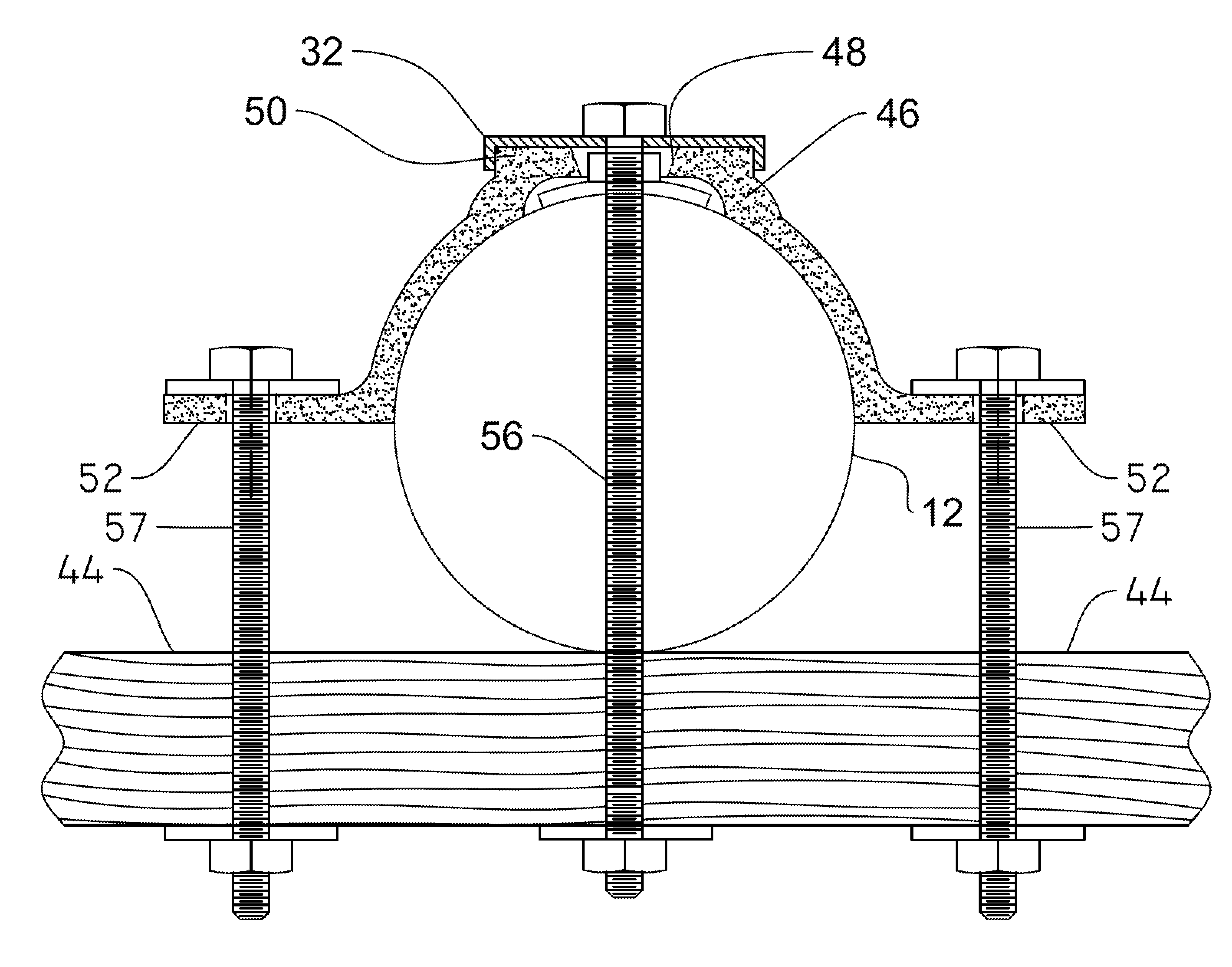
[0063]A fourth embodiment is depicted in FIGS. 5A, 5B, 6A, and 6B. This embodiment has utility in connection with upstanding poles 12 having a cross arm 44, with or without braces 44a. The perspective view of FIG. 6A depicts a certain embodiment of cross arm support member 46. Apertures 48 are formed in elongate support base 50 and may take the form of a circular opening or an elongated slot as depicted. A ninety degree bend forms vertical flange 52 enabling attachment of vertical cross arm support member 46 to cross arm 44 as depicted in FIGS. 5A and 5B. As illustrated in FIG. 6B, through bolts 57 pass through apertures 48 on flanges 52 into cross arm 44 to secure vertical cross arm support member 46 to cross arm 44.

[0064]As depicted in FIG. 5A, bolt 56 is inserted into pole 12 through aperture 48 to secure cross arm support member 46 to said pole. Cross arm support member 46 is positioned on pole 12 so that flange 52 serves as a support surface for cross arm 44 at generally the mi...

fifth embodiment

[0066]A fifth embodiment is depicted in FIGS. 7, 8A and 8B. Main body 62 of brace 60 is cylindrical. Legs 64a, 64b depend from cylindrical main body 62 in diametrically opposed relation to one another. The upper rim of main body 62 is denoted 62a. Apertures collectively denoted 63 are formed in cylindrical main body 62 in circumferentially and longitudinally spaced relation to one another and apertures collectively denoted 65 are formed in legs 64a, 64b.

[0067]As depicted in FIG. 8A, upper rim 62a of cylindrical main body 62 projects above the uppermost end 12a of pole 12 when brace 60 is properly installed in ensleeving relation to a pole top. Skirt 66 of top cap 68 has a length equal to or just slightly less than the distance of rim 62a above pole top 12A so that said skirt fits within the hollow interior of cylindrical main body 62 when top cap 68 is in its functional position as depicted in FIG. 8B. The diameter of skirt 66 causes it to fit tightly with a good friction fit withi...


PUM


Abstract

An apparatus for reinforcing an upstanding utility / meter pole having a worn top includes an elongate brace adapted to bear against the pole near a top end of the pole. A washer plate is disposed in overlying relation to the elongate brace. A front support is secured to an opposite side of the pole by an elongate bolt that extends diametrically through the pole and is engaged by a nut to secure the brace and front support in sandwiching relation to the pole. A second embodiment reinforces a cross arm of a pole and a third embodiment ensleeves a pole at its uppermost end in a cylindrical body that serves as a prosthesis for a disintegrating pole top.

Description

CROSS-REFERENCE TO RELATED APPLICATIONS[0001]This nonprovisional application is a continuation-in-part of and claims priority to nonprovisional application Ser. No. 14 / 624,845, entitled “UTILITY OR METER POLE TOP REINFORCEMENT METHOD AND APPARATUS,” filed Feb. 18, 2015, which is a divisional and claim priority to nonprovisional application Ser. No. 14 / 082,824, entitled “UTILITY OR METER POLE TOP REINFORCEMENT METHOD AND APPARATUS,” filed Nov. 18, 2013, by the same inventor.BACKGROUND OF THE INVENTION[0002]1. Field of the Invention[0003]This invention relates, generally, to repair of upstanding poles such as utility poles. More particularly, it relates to methods and apparatuses for strengthening the tops of poles that have structurally deteriorated over time to avoid or delay the cost of replacing such poles.[0004]2. Description of the Prior Art[0005]Utility poles become degraded over time near the ground and also at their upper end. There are many patented devices for strengthening...

Claims


Application Information

Patent Timeline
Patent Type & Authority Patents(United States)
IPC IPC(8): E04H12/22E04H12/24E04H12/04E04B1/38H02G7/20
CPCE04H12/24E04H12/04E04H12/2292E04B2001/405H02G7/20E04B2001/389
Inventor BUTLER, ROBERT P.
Owner PLS TECH
Why Eureka
Try Eureka