Solids discharge centrifugal separator with disposable contact elements

a centrifugal separator and contact element technology, applied in centrifugal force sediment separation, centrifugal process, centrifugal force, etc., can solve the problems of poor yield, damage, sensitive chemical or biological substances such as intact cells, etc., to eliminate the need for clean-in-place, and reduce the need for cleaning

Active Publication Date: 2010-07-01
CARR ROBERT BRET
View PDF69 Cites 15 Cited by
  • Summary
  • Abstract
  • Description
  • Claims
  • Application Information

AI Technical Summary

Benefits of technology

[0005]In accordance with the present invention, a centrifugal separator is disclosed that efficiently recovers sticky solids and exhibits low-shear filling and acceleration of feed material, while accommodating disposable process contacting elements to eliminate the need for clean-in-place and sterilize-in-place operations. Disposable elements of the separator are made of materials that are inexpensive enough to be considered by the user as suitable for single use, and therefore are generally made of plastic rather than metal, although the presence of some metal, rubber, or other materials in disposable elements is possible. Disposable elements also can be supplied and packaged as pre-sterilized units, and their use can avoid the need for cleaning and sterilizing steps during operation. The separator also can be operated in a hermetically sealed configuration. The separator can be particularly useful for sensitive solids such as chemical or biological substances. A separator of the invention can recover sensitive solids, liquids, materials or combinations thereof without operator intervention or additional mechanical equipment.

Problems solved by technology

For example, some separators may not be capable of completely discharging solids that are sticky, which can result in poor yields.
A poor yield can be especially problematic for high-value solids such as those encountered in pharmaceutical processes.
Traditional separators also subject a feed material to very high shear forces when accelerating the material to the rotational speed of the bowl, which can damage, for example, sensitive chemical or biological substances such as intact cells.
Other separators do not provide a convenient means by which to handle and recover sensitive solids.
For example, an operator is commonly required to assist with solids discharge and recovery, introducing the potential for contamination.
Furthermore, conventional separators tend to be difficult to clean or sterilize in place, requiring operations that significantly increase maintenance costs and creating the potential for cross contamination between different preparations.
Nevertheless, to our knowledge no available separator offers the advantages of fully pre-sterilizable and disposable sample contacting elements.

Method used


Image

  • Solids discharge centrifugal separator with disposable contact elements
  • Solids discharge centrifugal separator with disposable contact elements
  • Solids discharge centrifugal separator with disposable contact elements

Examples


Embodiment Construction

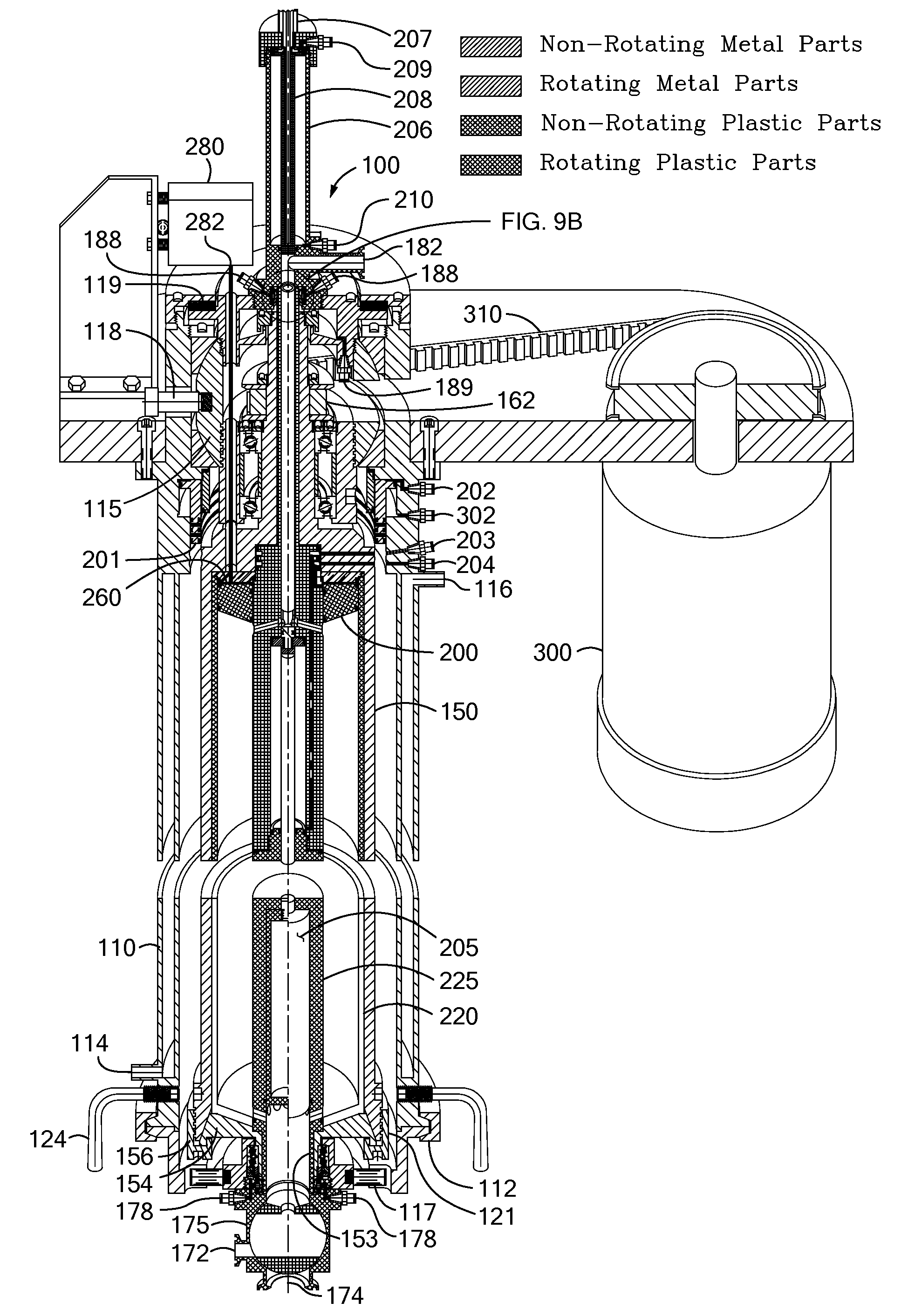
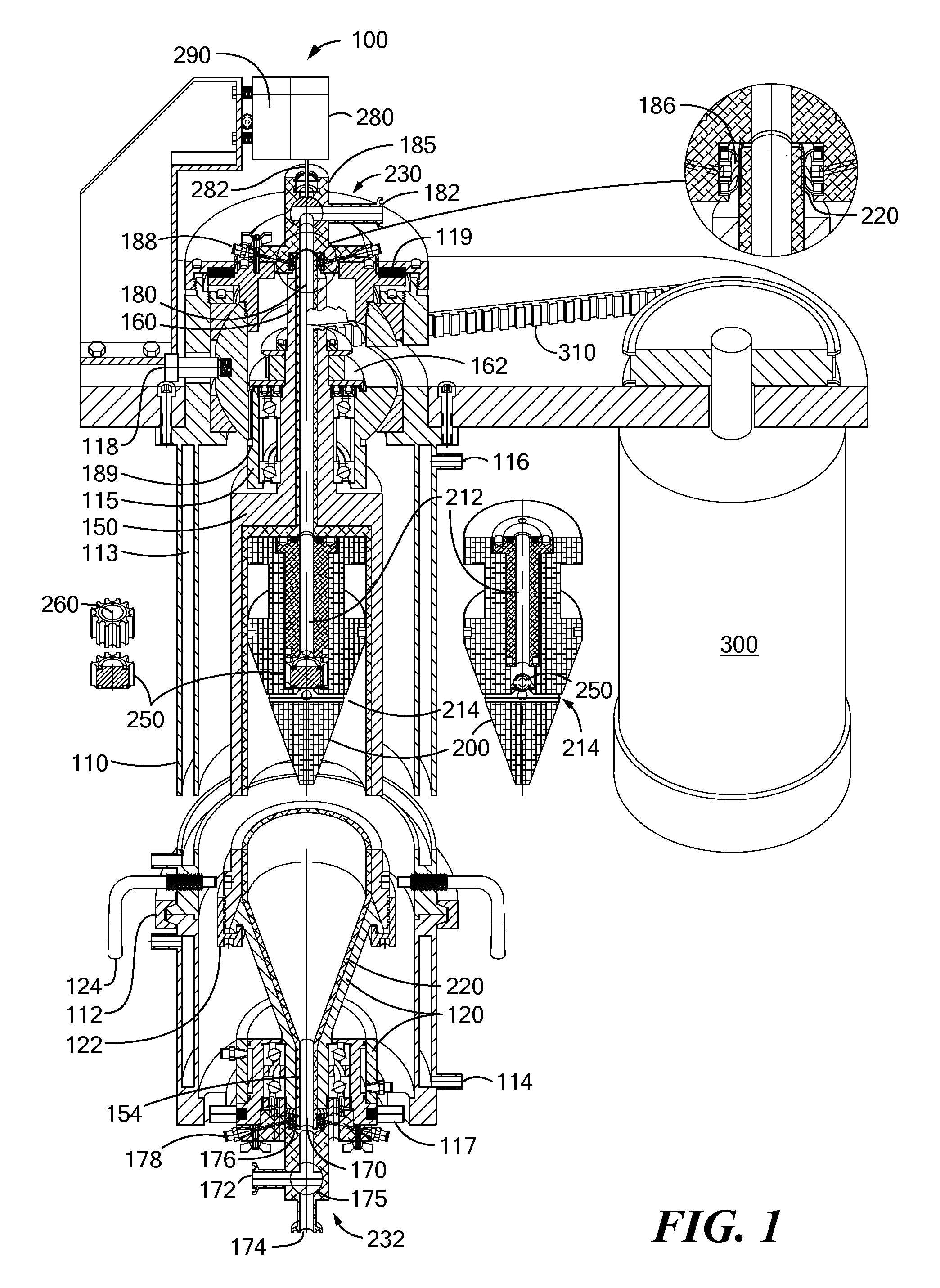
[0041]FIG. 1 shows an embodiment of a centrifugal separator according to the invention in vertical section, with a middle section removed. Separator 100 includes separator bowl 150, separator housing 110, and variable speed drive motor 300.

[0042]The housing has upper, middle, and lower portions. The middle portion of the separator housing encloses separator bowl 150. In the embodiment shown in FIG. 1 this portion of the housing is temperature controlled by fluid jacket 113 for flowing a controlled temperature fluid, such as water, in through cooling inlet port 114 in the lower portion of the housing and out through cooling outlet port 116 near the top of the middle portion of the housing. Depending on the application the fluid jacket of the housing can be used either to cool or warm the centrifuge interior, and therefore the sample during separation. In separations of sensitive materials such as cell suspensions it is typical to cool the centrifuge using cooling water, for example t...


PUM

PropertyMeasurementUnit
diameteraaaaaaaaaa
diameteraaaaaaaaaa
temperatureaaaaaaaaaa

Abstract

A hermetically sealed solids discharge centrifugal separator exhibits low-shear filling, acceleration, and separation of feed material. The separator can be particularly useful for separation and recovery of sensitive solids such as chemical or biological substances. The separator accommodates disposable sample contacting elements to eliminate the need for clean-in-place and sterilize-in-place operations. Some embodiments of the separator feature dual solids discharge pistons, which fully optimize recovery of valuable solids.

Description

CROSS REFERENCE TO RELATED APPLICATIONS[0001]This application claims the priority of U.S. Provisional Application No. 61 / 141,040, filed Dec. 29, 2008 entitled, SOLIDS DISCHARGE CENTRIFUGAL SEPARATOR WITH DISPOSABLE CONTACT ELEMENTS, the whole of which is hereby incorporated by reference.BACKGROUND OF THE INVENTION[0002]Many different types of centrifugal separators are known for separating heterogeneous mixtures into components based on specific gravity. Typically, a heterogeneous mixture, which may also be referred to as feed material or liquid, is injected into a rotating bowl of a centrifugal separator. The rotating bowl spins at high speeds and forces components of the mixture that have a high specific gravity to separate therefrom by sedimentation. As a result, dense solids compress as a cake tightly against an inner surface or wall of the bowl and clarified liquid, or centrate, forms radially inward from the cake. The bowl may spin at speeds sufficient to produce forces 20,000...

Claims


Application Information

Patent Timeline
Patent Type & Authority Applications(United States)
IPC IPC(8): B04B9/10B04B1/18B04B15/00B04B15/02B04B13/00B04B7/12
CPCB04B7/12B04B9/08B04B9/12B04B11/02B04B11/04B04B13/00B04B15/02B04B2005/0485B04B11/05
Inventor CARR, ROBERT B.
Owner CARR ROBERT BRET
Why Eureka
Try Eureka