
Locating structure for plaster trowel

Inactive Publication Date: 2005-10-27
WANG SEE TUH
View PDF5 Cites 5 Cited by
  • Summary
  • Abstract
  • Description
  • Claims
  • Application Information

AI Technical Summary

Benefits of technology

[0013] 2. By this improved structure, when assembling the grip and the fixation frame, the grip may be connected to the connecting rod of the fixatio

Problems solved by technology

Thus, in terms of both the components and assembly, it is costly and fails to meet the demand of industry.

Method used


Image

  • Locating structure for plaster trowel
  • Locating structure for plaster trowel
  • Locating structure for plaster trowel

Examples


Embodiment Construction

[0024] The features and the advantages of the present invention will be more readily understood upon a thoughtful deliberation of the following detailed description of a preferred embodiment of the present invention with reference to the accompanying drawings.

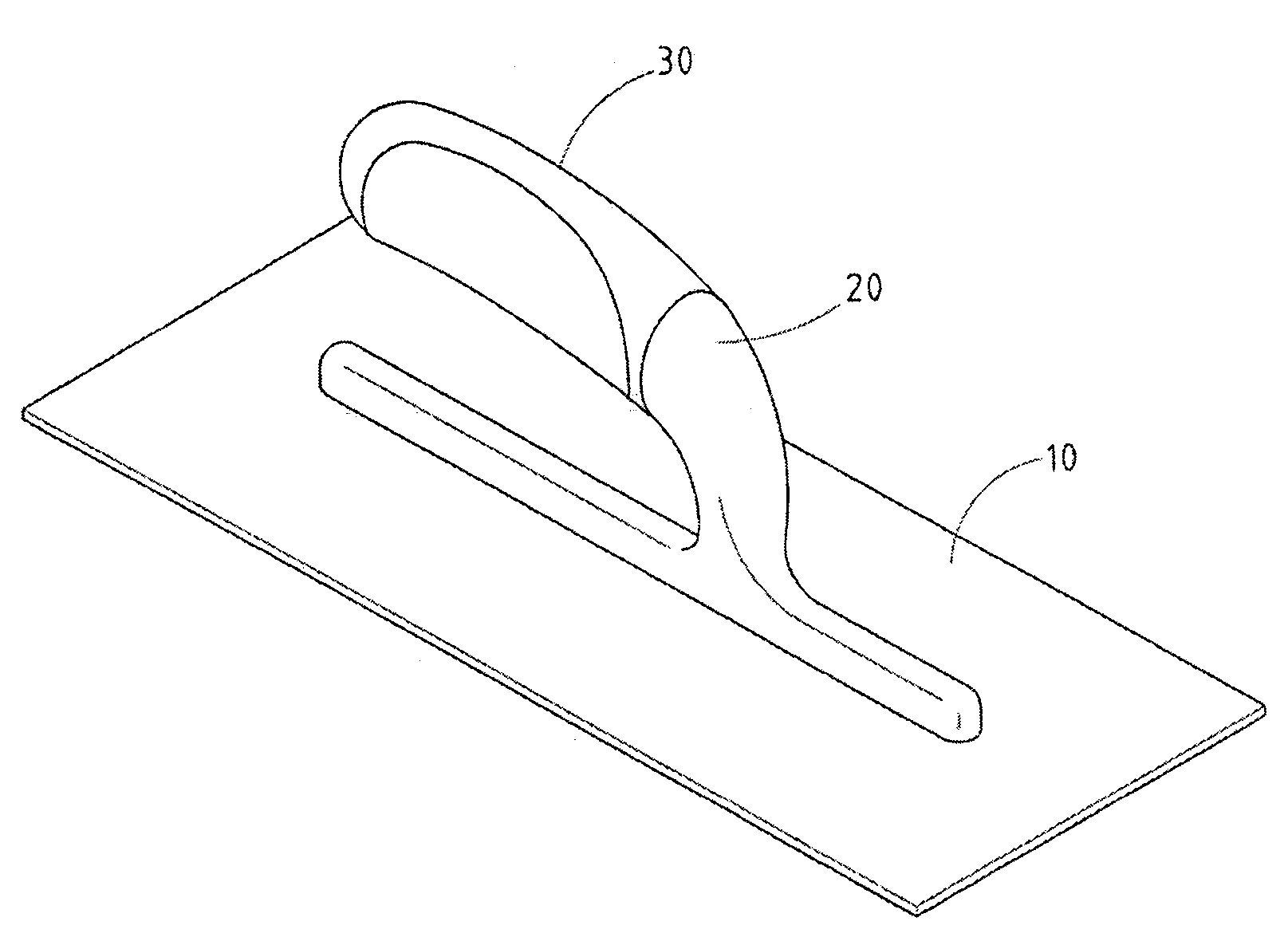
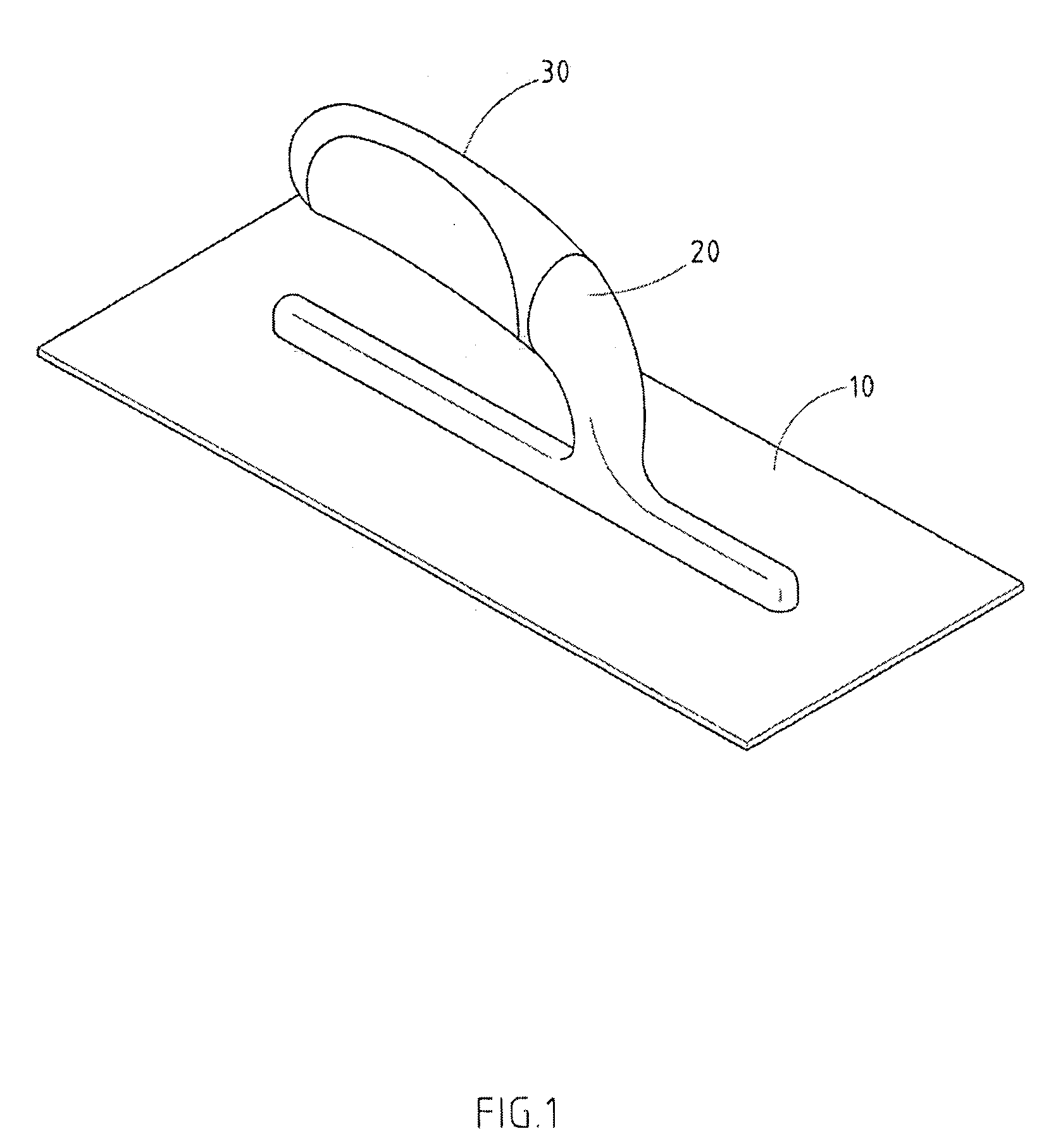
[0025] As shown in FIGS. 1-5, there is a locating structure for plastic trowel embodied in the present invention.

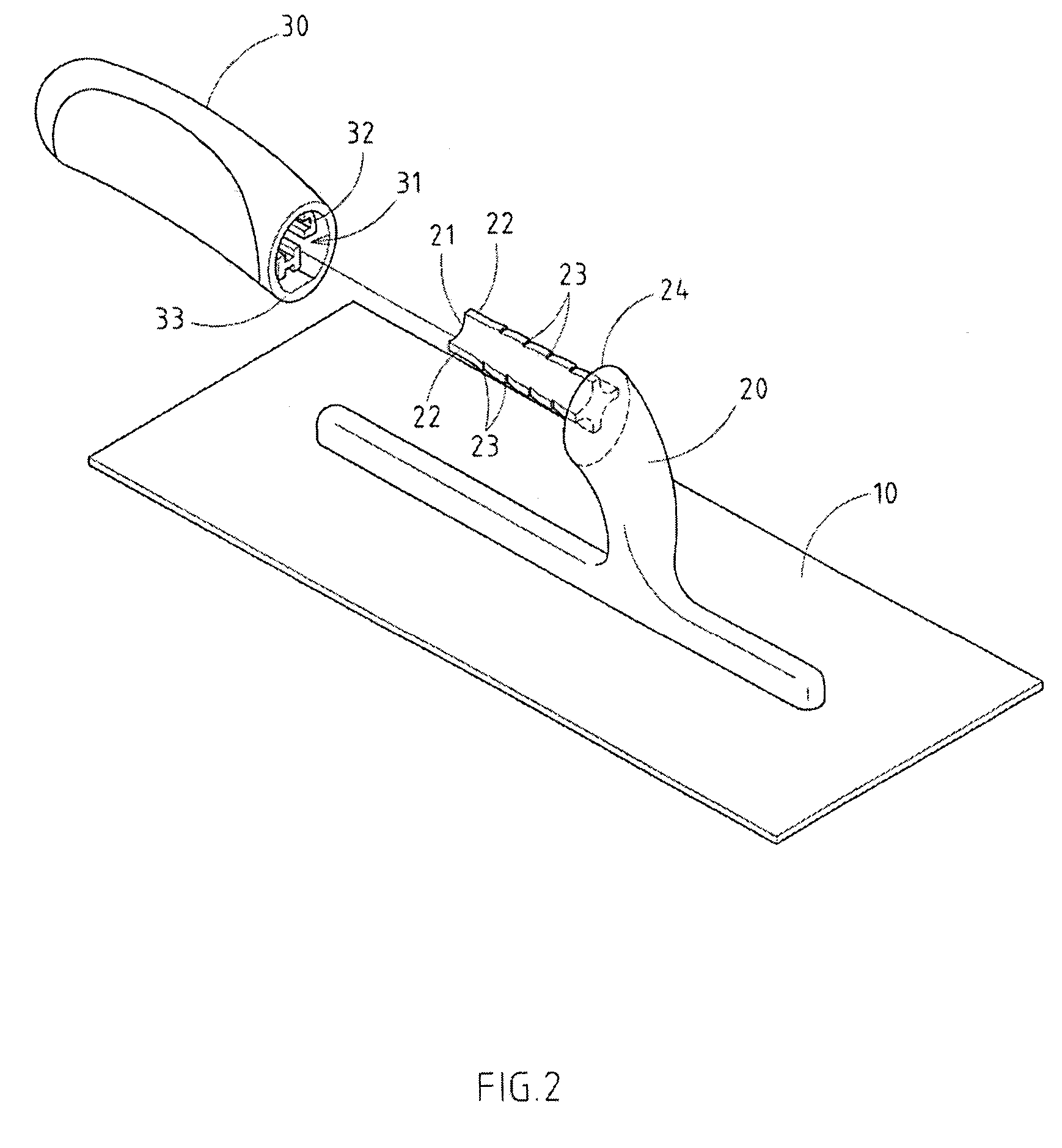
[0026] The invention has a low profile 10, a fixation frame 20 on the side of low profile 10, and a grip 30 that connects to the connecting rod 21 of the said fixation frame 20; and the said grip has groove hole that can be connected to the connecting rod 21 of the fixation frame 20.

[0027] The connecting rod 21 of the fixation frame 20 has several radial protruding ribs 22, and each protruding rib 22 has monoclinal jagged edge 23 on the sides; the side groove 32 that locks the groove hole 31 of the grip 30 and each protruding rib 22 of the connecting rod 21 mentioned above.

[0028] By the above mentioned structure ...


PUM


Abstract

The locating structure for the grip of the plaster trowel includes a low profile, a fixation frame on one side of the low profile, and a grip that connects to this fixation frame through the connecting rod. This grip has a groove hole that connects to the connecting rod of the fixation frame; the side groove that locks the groove hole of the grip and each protruding rib of the connecting rod. By this improved structure, when assembling the grip and the fixation frame, the grip may be connected to the connecting rod of the fixation frame to achieve the axial and radial locating effect, which shortens the time involved in assembling to reduce the cost by using simple components.

Description

RELATED U.S. APPLICATIONS [0001] Not applicable. STATEMENT REGARDING FEDERALLY SPONSORED RESEARCH OR DEVELOPMENT [0002] Not applicable. REFERENCE TO MICROFICHE APPENDIX [0003] Not applicable. FIELD OF THE INVENTION [0004] The present invention relates generally to a plaster trowel, and more particularly to a locating structure that improves a grip and fixation frame for the plaster trowel. BACKGROUND OF THE INVENTION [0005] The grip of the plaster trowel is usually located on one side of the low profile of the plaster trowel for the user to hold and operate, and they are generally connected by the fixation frame. The objective of the present invention is to improve the locating structure that connects the grip and the fixation frame, and its known structure, published in the Taiwanese National Official Gazette of Patent No 371975 (see the attachment). The main features include a through hole 33 that is built in the grip 30, and after a connecting rod 25, which is placed crosswise to...

Claims


Application Information

Patent Timeline
IPC IPC(8): B05C17/10B25G3/14B25G3/34E04F21/06E04F21/16
CPCB25G3/14E04F21/161B25G3/34
Inventor WANG, SEE-TUH
Owner WANG SEE TUH
Features
  • Generate Ideas
  • Intellectual Property
  • Life Sciences
  • Materials
  • Tech Scout
  • Unparalleled Data Quality
  • Higher Quality Content
  • 60% Fewer Hallucinations
Learn More