Roll-down tube for a pneumatic spring

a technology of pneumatic spring and roller, which is applied in the direction of mechanical equipment, shock absorbers, transportation and packaging, etc., can solve the problems of increasing the weight of the component, increasing the cost of production, and avoiding areas with increased concentrations of materials, so as to achieve favorable stiffening ribs, more functional internal contours, and favorable material distribution

Inactive Publication Date: 2005-10-27
ZF FRIEDRICHSHAFEN AG
View PDF11 Cites 19 Cited by
  • Summary
  • Abstract
  • Description
  • Claims
  • Application Information

AI Technical Summary

Benefits of technology

[0007] The great advantage of the invention is that a more functional internal contour can be produced, regardless of the way in which the roll-down tube itself is manufactured. In the case of a roll-down tube made out of injection-molded plastic, therefore, more favorable material distributions can be provided and more favorable stiffening ribs obtained.
[0008] It is simpler, in general, for the parting line to be parallel to the longitudinal axis of the roll-down tube. For the purpose of improving the seal between the individual shell-like elements, however, at least one parting line between the individual elements should extend at an angle to the longitudinal axis. When an axial load acts on the individual elements, the elements will thus be clamped together in the area of the parting line.
[0009] In another advantageous embodiment, sealing means are provided between the individual elements. When the sealing means are sprayed onto the individual element, the contour of the parting line(s) can be designed with greater freedom, because there is no need to depend on prefabricated sealing strips or sealing rings. The extra labor required to install a separate sealing ring is also eliminated.
[0010] It is also provided that one of the individual elements has at least one axial support surface for at least one other individual element. The axial support surface prevents the two individual elements from being pushed beyond their final assembly position with respect to each other.
[0011] In addition, at least one locking means on at least one of the individual elements secures the individual elements with respect to each other in their final assembly position. The roll-down tube thus forms a closed structural unit.
[0012] An effective way to prevent the locking means from being opened is to design the locking means in the form of at least one snap hook, which acts on the minimum of one other individual element.

Problems solved by technology

If, when this design principle is applied, the mid-section of the roll-down tube is pulled inward to a significant degree, it is impossible to avoid areas with increased concentrations of material.
This extra material increases the cost of production, increases the weight of the component, and also interferes with the injection-molding properties, because a nonuniform distribution of material means that the rate at which the material inside the component cools will differ from one place to another.
In addition, it can be expected that the component will warp, so that, under certain conditions, it will be impossible to obtain the desired dimensional accuracy.

Method used


Image

  • Roll-down tube for a pneumatic spring
  • Roll-down tube for a pneumatic spring
  • Roll-down tube for a pneumatic spring

Examples


Embodiment Construction

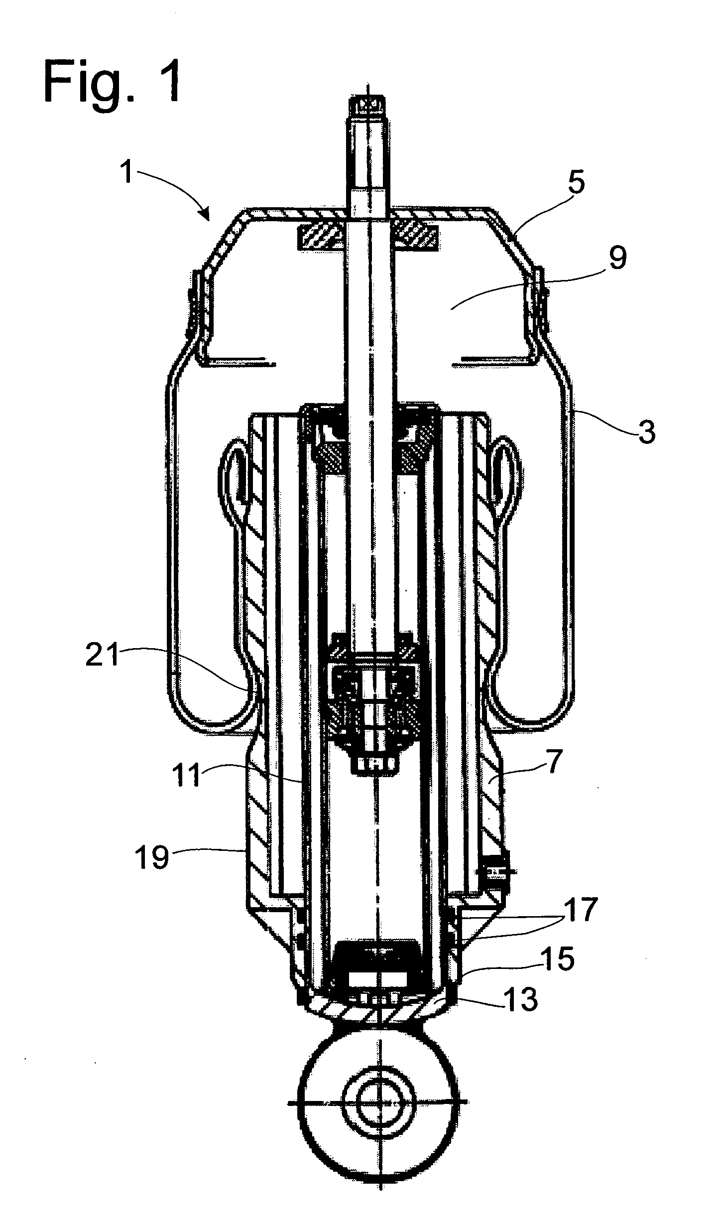
[0029]FIG. 1 shows a pneumatic spring 1 such as that known from DE 88 13 045 U1. The pneumatic spring 1 includes a rolling bellows 3, one end of which is connected by a clamping ring to a cap 5, whereas the other end is connected to a roll-down tube 7. The sealed cap 5, the rolling bellows 3, and the roll-down tube 7 define a gas-filled spring space 9, which exerts a load-bearing force. In this application example of a pneumatic spring, a vibration damper is mounted coaxially to the roll-down tube; this damper has a container tube 11, to which a support ring 13 is attached. The roll-down tube is supported axially by its bottom end surface 15 against the container tube. So that no pressure can be lost, the pneumatic spring has at least one sealing ring 17.

[0030] During a force-absorbing movement, the rolling bellows rolls down along the outside wall 19 of the roll-down tube. The necked-down section 21 makes the spring force characteristic of the pneumatic spring dependent on the str...


PUM


Abstract

A roll-down tube for a pneumatic spring which is fitted to a shock absorber having a cylinder tube and a piston rod, the roll-down tube having an internal contour which is fitted to the cylinder tube and a longitudinal axis corresponding to the piston rod. The pneumatic spring includes a rolling bellows having one end fitted to a cap fixed to the piston rod and another end fixed to the roll-down tube, the roll-down tube being formed by two molded plastic shells which are fitted together.

Description

BACKGROUND OF THE INVENTION [0001] 1. Field of the Invention [0002] The invention relates to a roll-down tube for a pneumatic spring which is fitted to a shock absorber having a cylinder tube and a piston rod, the roll-down tube having an internal contour which is fitted to the cylinder tube and a longitudinal axis corresponding to the piston rod, the pneumatic spring including a rolling bellows having one end fitted to a cap fixed to the piston rod and another end fixed to the roll-down tube. [0003] 2. Description of the Related Art [0004] A roll-down tube for a pneumatic spring is known from DE 88 13 045 U1. The roll-down tube consists of plastic, where the essential advantage is that the relatively complicated roll-down contour and a high-quality surface finish can be produced more cheaply out of plastic than out of metal. The roll-down tube described in DE 88 13 045 U1 has a comparatively simple internal contour with undercut-free axial webs. If, when this design principle is ap...

Claims


Application Information

Patent Timeline
Patent Type & Authority Applications(United States)
IPC IPC(8): F16F9/05
CPCF16F9/057B60G2206/424
Inventor GROSS, ALEXANDERGUBITZ, HOLGERNOWOTKA, THOMAS
Owner ZF FRIEDRICHSHAFEN AG
Why Eureka
Try Eureka