Steering device

Inactive Publication Date: 2005-10-27
NSK LTD
View PDF24 Cites 20 Cited by
  • Summary
  • Abstract
  • Description
  • Claims
  • Application Information

AI Technical Summary

Benefits of technology

[0005] The present invention has been made in view of the problems of these conventional techniques, and it is an object of the present invention to provi

Problems solved by technology

However, at this time, the other bracket is pressed via the support member, and this might cause an axis deviation of the steering shaft.
However, this might induce rises both in weight and in

Method used


Image

  • Steering device
  • Steering device
  • Steering device

Examples


first embodiment

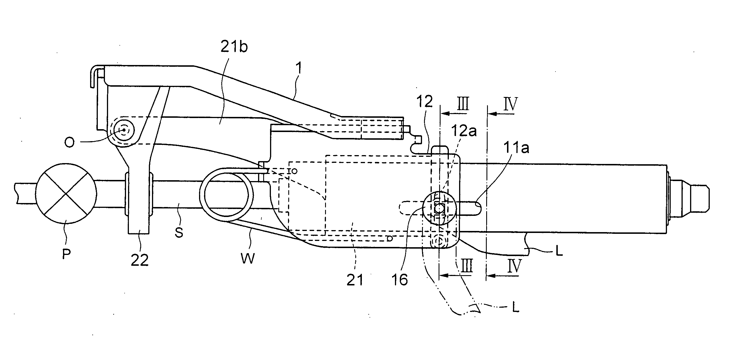
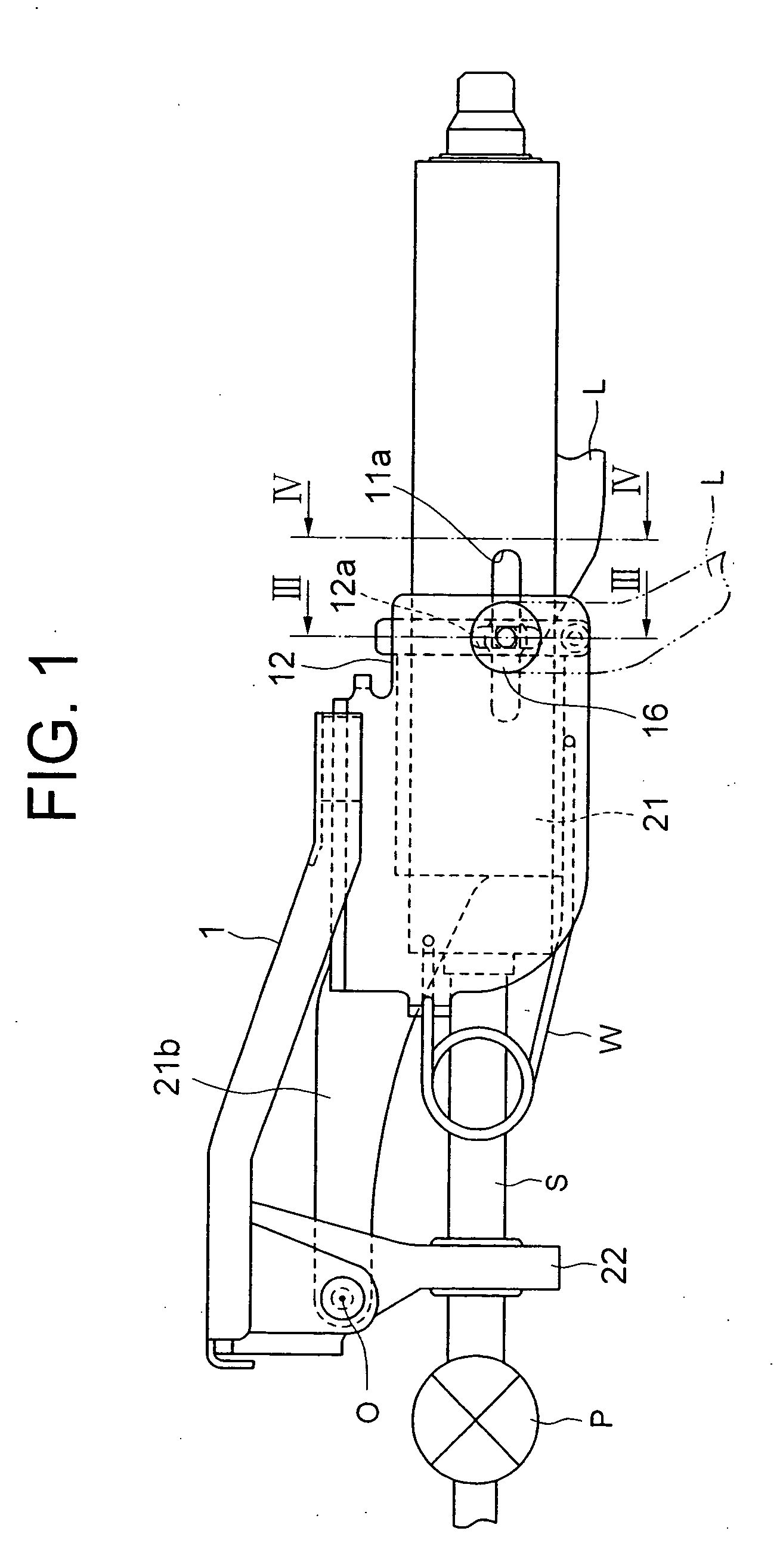
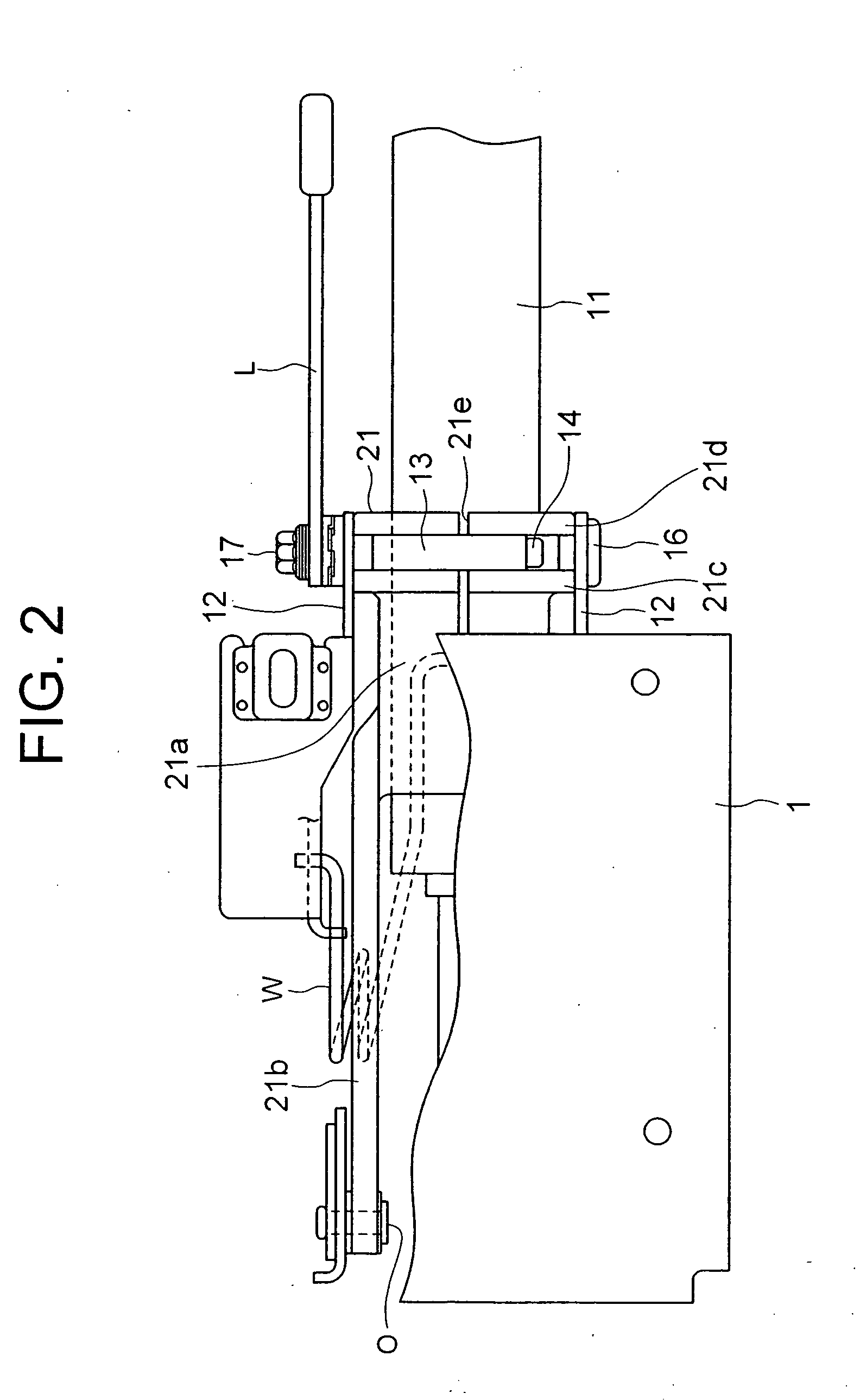
[0031] In the following, a description will be given of a tilt / telescopic type steering apparatus according to embodiments of the present invention with reference to the drawings. FIG. 1 is a side view of the tilt / telescopic type steering apparatus according to the present invention. FIG. 2 is a top view of the steering apparatus shown in FIG. 1. FIG. 3 is a view showing the configuration in FIG. 1, cut off by the line III-III as viewed in the arrow direction, and FIG. 4 is a view showing the configuration in FIG. 1, cut off by the line IV-IV as viewed in the arrow direction. A steering shaft is omitted in the respective figures. FIG. 5 is a bottom view of an end part of an outer column, showing the shape of a slit 21e described below.

[0032] Referring to FIG. 3, two pieces of brackets 12 each composed of a plate material bent in an L-shape, are attached through a pair of release capsules 15 to a top plate 1 secured to an unillustrated car body. A plate thickness of each of the brack...

second embodiment

[0050]FIG. 8 is a view, similar to FIG. 7, of a tilt / telescopic type steering apparatus according to the present invention. The present embodiment is different from the above-described embodiment merely in the point in which the slit 21e of the outer column 21′ is provided only at the lower side, and thus common components other than that are marked with the same numerals and symbols, the descriptions of which are omitted.

[0051] In the present embodiment, since the outer column 21′ does not have an upper slit, when a pressing force is applied to the outer column 21′ from the both sides in FIG. 8, flange parts 21c, 21d are deformed to close the lower slit 21e with a fulcrum point P3 as a center, thereby making it possible to hold the inner column 11.

[0052] Here, in the comparative example, shown in FIG. 6, in which the centers of the fixing members 16, 17 intersect the axis line of the inner column 11, assuming that a pressing force, which is given by the fixing members 16, 17 neces...

third embodiment

[0055]FIG. 9 is a view, similar to FIG. 3, of a tilt / telescopic type steering apparatus according to the present invention. In the present embodiment, a line R connecting centers of the fixing members 16′, 17′ is shifted upward in FIG. 9 with respect to the axis line X of the inner column 11. Also, the fixing members 16′, 17′ are not provided with telescopic guided portions, the ends thereof are not inserted in the outer column 21′ and the inner column 11′. Accordingly, it is not necessary to provide the outer column 21′ and the inner column 11′ with telescopic grooves, respectively. The other components are common with those of the structure shown in FIG. 3, thus they are marked with the same numerals and symbols, and the descriptions thereof are omitted.

[0056] The present invention has been explained in depth so far with reference to the embodiments. The present invention should not, however, be construed as limited to the embodiments described above and can be, as a matter of cou...


PUM


Abstract

To provide a steering apparatus having an excellent operationality and capable of suppressing backlash and preventing an axis deviation of the steering shaft. A line R connecting the centers of two fixing members 16, 17 is shifted with respect to an axis line of an inner column 11, and thus a component Fv of a force transmitted from the fixing members 16, 17 to the inner column 11 via an outer column 21 is applied to press the inner column 11 in a direction orthogonal to the line R connecting the centers of the two fixing members 16, 17. It is, therefore, possible to reduce backlash between the inner column 11 and the outer column 21.

Description

TECHNICAL FIELD [0001] The present invention relates to a tilt / telescopic type steering apparatus capable of adjusting a tilt angle of a steering wheel and an axis-directional position thereof, corresponding to a driving posture (position) of a driver. BACKGROUND ART [0002] What is known as a steering apparatus for an automotive vehicle is a tilt / telescopic type steering apparatus capable of adjusting a tilt angle of a steering wheel and an axis-directional position of the steering wheel, corresponding to a physique and a driving posture of a driver. [0003] Here, there is an idea that components of the tilt / telescopic type steering apparatus are disposed as close to a steering shaft as possible in order to ensure a space in the vicinity of knees of the driver. Based on this idea, Japanese Patent Application Laid-Open No. 2001-191927 discloses a steering apparatus constructed such that support members disposed within a steering column are interposed between a pair of brackets and are...

Claims


Application Information

Patent Timeline
IPC IPC(8): B62D1/184B62D1/187
CPCB62D1/187B62D1/184
Inventor SAWADA, NAOKIIKEDA, SHUHEIYAMADA, JUN
Owner NSK LTD
Why Eureka
Try Eureka