
Apparatus, system and method for virtual user interface

user interface technology, applied in the field of apparatus, a system and a virtual user interface, can solve the problems of mobile products with such uncomfortable grips, failures on the market, and difficulty in accurately examining the grip of users with respect to a substantial object,

Inactive Publication Date: 2005-10-27
SAMSUNG ELECTRONICS CO LTD
View PDF20 Cites 31 Cited by
  • Summary
  • Abstract
  • Description
  • Claims
  • Application Information

AI Technical Summary

Benefits of technology

[0009] To address the above drawbacks of the conventional arrangement, as well as others, an aspect of the present invention provides an apparatus, a system, and a method for a virtual user interface, capable of displaying a virtual...

Problems solved by technology

Grips that are uncomfortable cause the user to become fatigued and are inconvenient.
A mobile product, with such an uncomfortable grip, can become a failure on the market, albeit having high performance.
It is, however, difficult to accurately examine the grip of the user with respect to a substantial object To accurately examine the grip, a mock-up is built using a chemical wood at a point in the development phase when appearance of the mobile product is finally designed.
It requires a great deal of time and cost, however, to make the mock-up of the mobile product.
What is worse, the mobile product that has a complicated shape increases the required time and cost.
In addition, it is impossible to modify the shape of the mock-up after the creation.
Accordingly, a new mock-up has to be re-created to make up for design defects if it is determined that the created mock-up proves an uncomfortable grip or improper locations of the buttons; this, of course, requires additional time and cost.
Although the appearance of the mobile product and the locations of the buttons may be modified or altered at the development phase, this is not conducive to an efficient and economic design program.
In such situations, the re-creation of the mock-up causes enormous cost and time.

Method used


Image

  • Apparatus, system and method for virtual user interface
  • Apparatus, system and method for virtual user interface
  • Apparatus, system and method for virtual user interface

Examples


Embodiment Construction

[0023] Several embodiments of the present invention will now be described in detail with reference to the annexed drawings. In the drawings, the same or similar elements are denoted by the same reference numerals even though they are depicted in different drawings. In the following description, a detailed description of known functions and configurations incorporated herein have been omitted for conciseness and clarity.

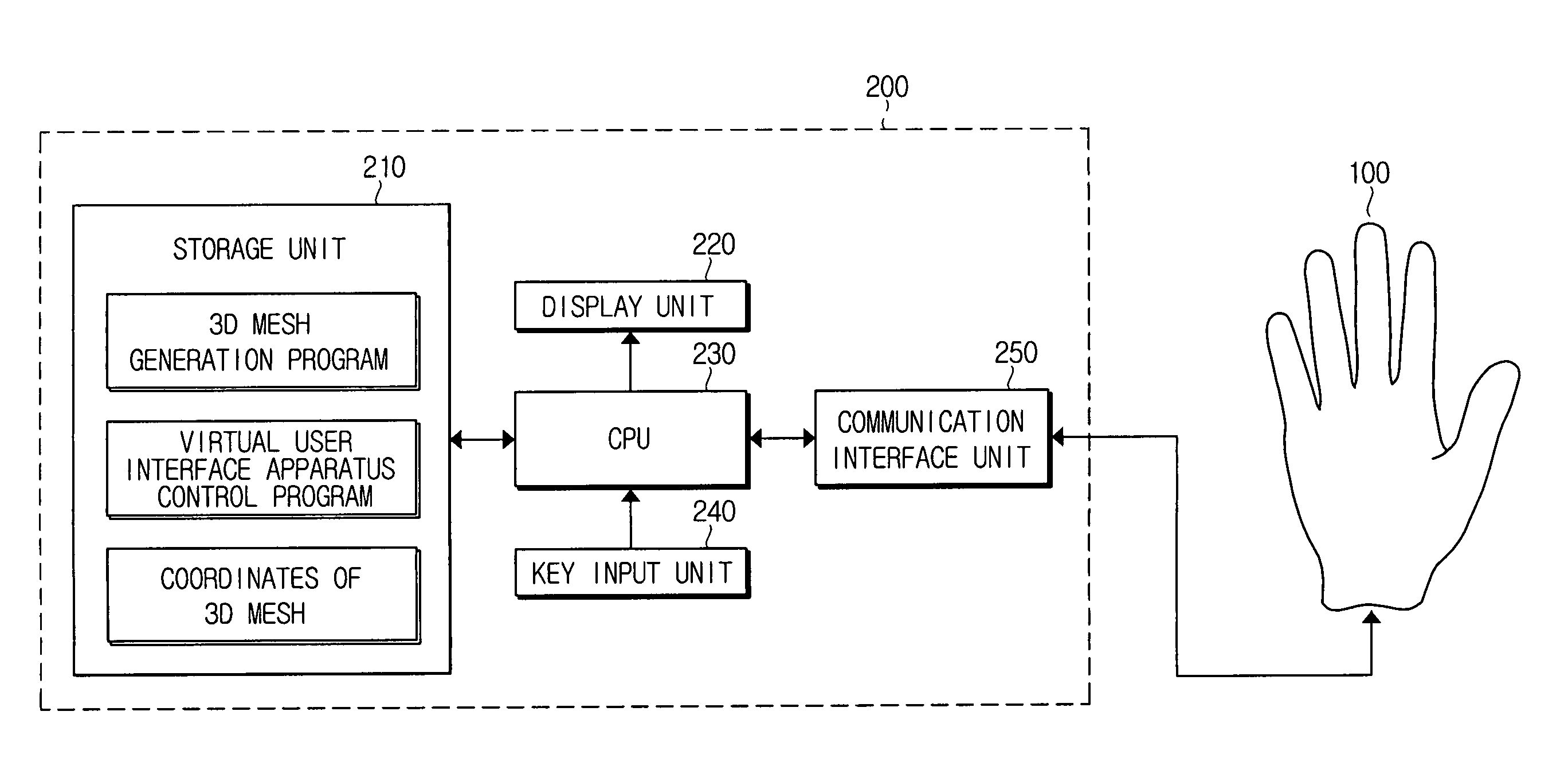
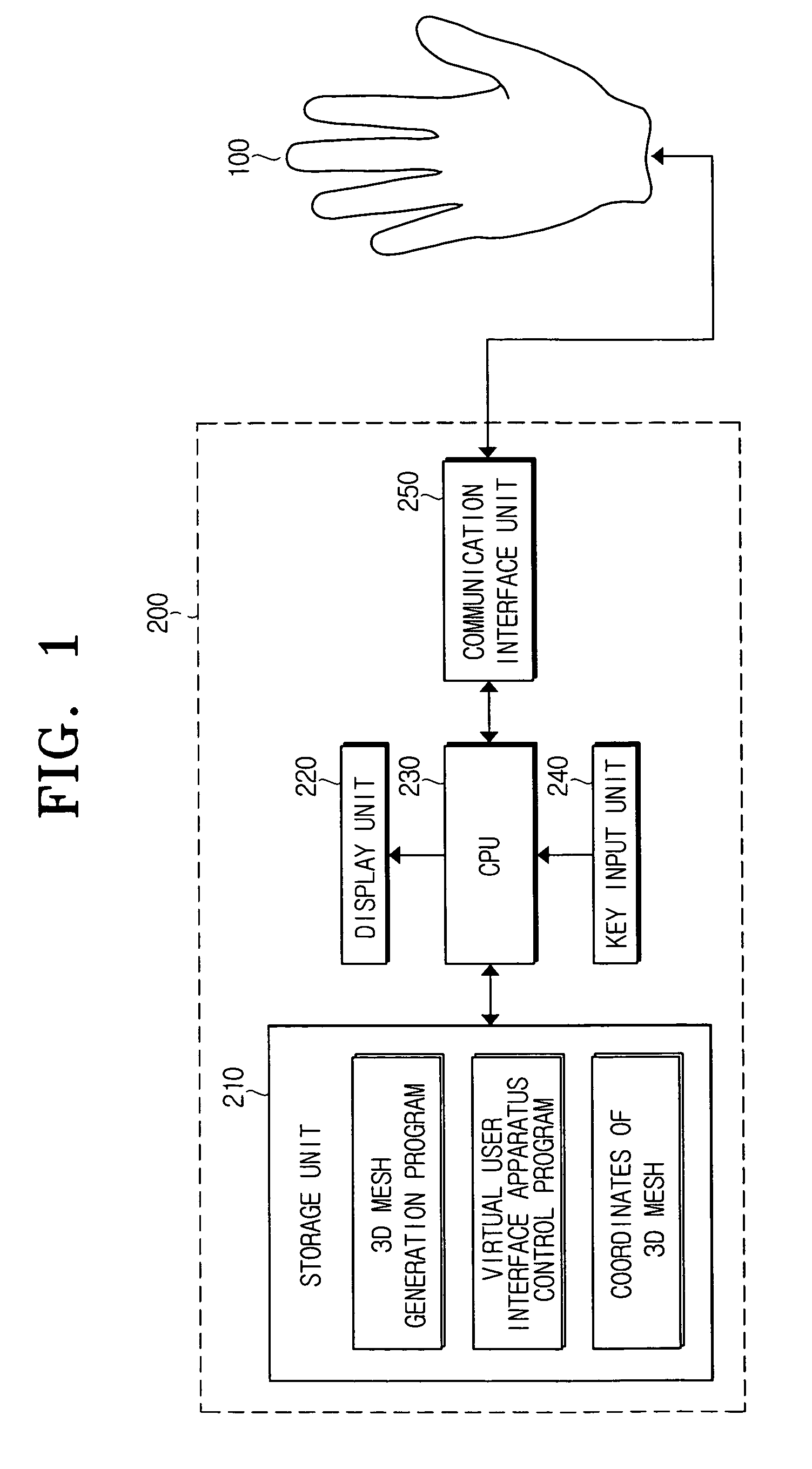
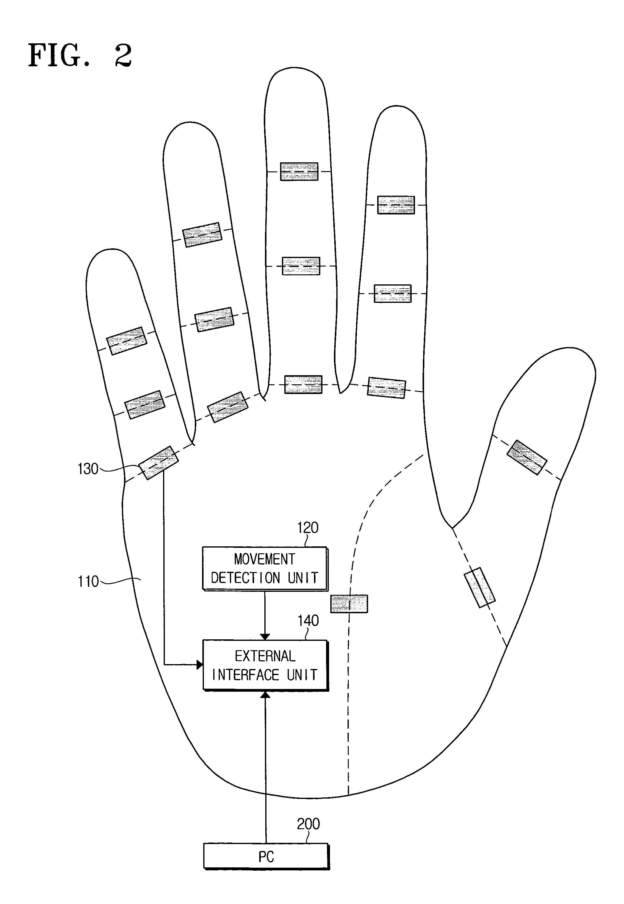
[0024]FIG. 1 is a schematic block diagram of a virtual user interface system according to an embodiment of the present invention. Referring to FIG. 1, the virtual user interface system includes a virtual user interface apparatus 100 and a personal computer (PC) 200, which is a host device. The PC 200 displays the motion of an actual hand of a user on a screen as it is, by processing data input from the virtual user interface apparatus 100. The PC 200 transfers a control signal to the virtual user interface apparatus 100 to restrain the motion of the user's actual han...


PUM


Abstract

A Virtual user interface apparatus, system, and method are provided, wherein the virtual user interface apparatus comprises a movement detection unit for detecting a movement degree of an actual hand, a bend detection and restriction unit for detecting a bend degree of a finger of the actual hand and restricting the bend of the finger when a control signal is received from a host device, and an external interface unit for transferring the detected movement degree and the bend degree to the host device, and receiving and transferring the control signal, which is generated by the host device by use of the movement degree, the bend degree, and information on a certain 3-dimensional shape, to the bend detection and restriction unit Accordingly, the grip of a product can be virtually examined without having to make a mock-up of the product. Thus, money and time are saved by not making a mock-up of the product

Description

CROSS-REFERENCE TO RELATED APPLICATIONS [0001] This application claims priority under 35 U.S.C. § 119(a) to an application entitled “APPARATUS, SYSTEM AND METHOD FOR VIRTUAL USER INTERFACE” filed in the Korean Intellectual Property Office on Apr. 23, 2004 and assigned Korean Patent Application No. 2004-28078, the entire contents of which are expressly incorporated herein by reference. BACKGROUND OF THE INVENTION [0002] 1. Field of the Invention [0003] The present invention generally relates to an apparatus, a system, and a method for a virtual user interface. More specifically, the present invention relates to an apparatus, a system, and a method for a virtual user interface, enabling to virtually feel a grip of a virtual 3-dimensional shape. [0004] 2. Description of the Related Art [0005] A mobile product such as a camcorder, a ca0000mera, and a mobile phone, needs to provide a user with soft and comfortable grip when the user utilizes the mobile product while holding the mobile pr...

Claims


Application Information

Patent Timeline
IPC IPC(8): G09G5/00H04M1/23
CPCG06F3/017G06F3/014
Inventor LEE, DONG-SEOK
Owner SAMSUNG ELECTRONICS CO LTD
Learn More