
Camera and control method for camera

a control method and camera technology, applied in the field of cameras and control methods, can solve the problems of difficulty for skilled users to understand information, unskilled users may not sufficiently comprehend the characteristic features of respective scenes,

Inactive Publication Date: 2005-10-27
WATANABE SAYURI
View PDF13 Cites 32 Cited by
  • Summary
  • Abstract
  • Description
  • Claims
  • Application Information

AI Technical Summary

Benefits of technology

[0009] According to an aspect of the present invention, it is an object to provide a camera and a control method for the camera which support the opera

Problems solved by technology

Even if, therefore, combinations of sample images and explanatory descriptions are presented on such a compact image display device, an unskilled user may not sufficiently co

Method used


Image

  • Camera and control method for camera
  • Camera and control method for camera
  • Camera and control method for camera

Examples


first embodiment

[0028] A first embodiment of the present invention will be described first.

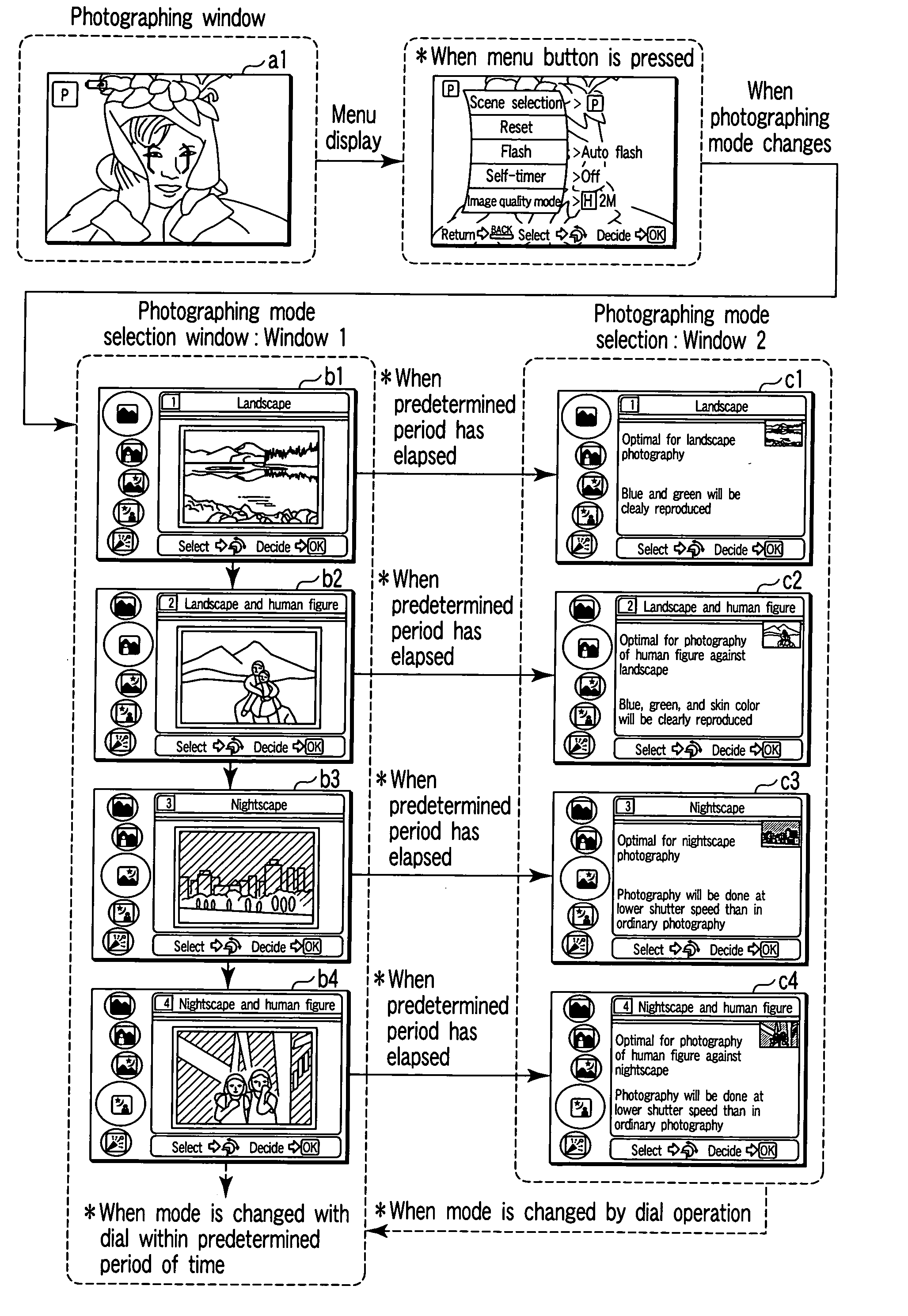
[0029] In the following description, the first explanatory image described above comprises an explanatory window b1, a storage unit comprises an EEPROM 32, the second explanatory image comprises an explanatory window c1, an icon image comprises icon images b21 to b25, the first sample image comprises a sample image b11, and the second sample image comprises a sample image c11.

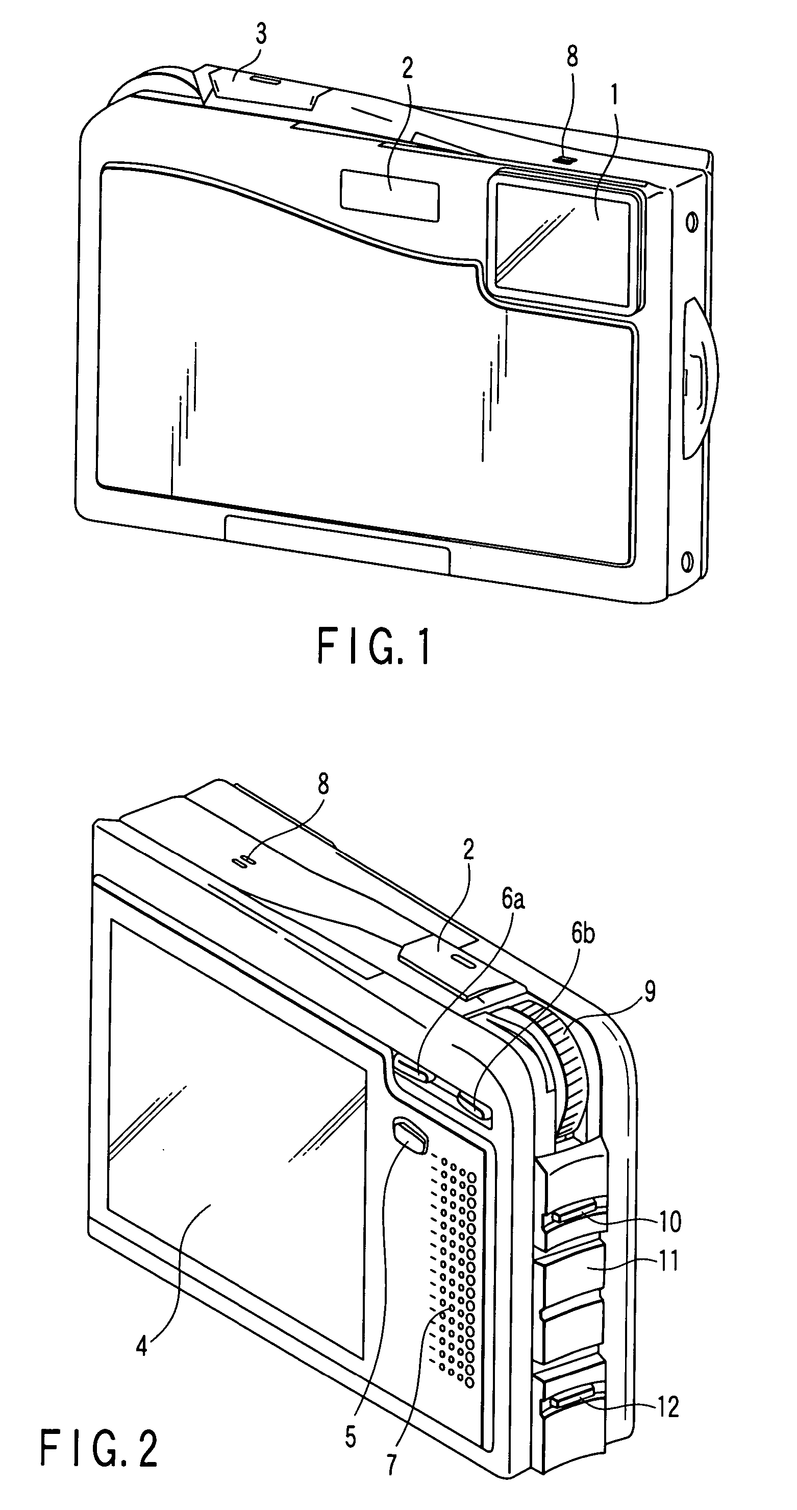
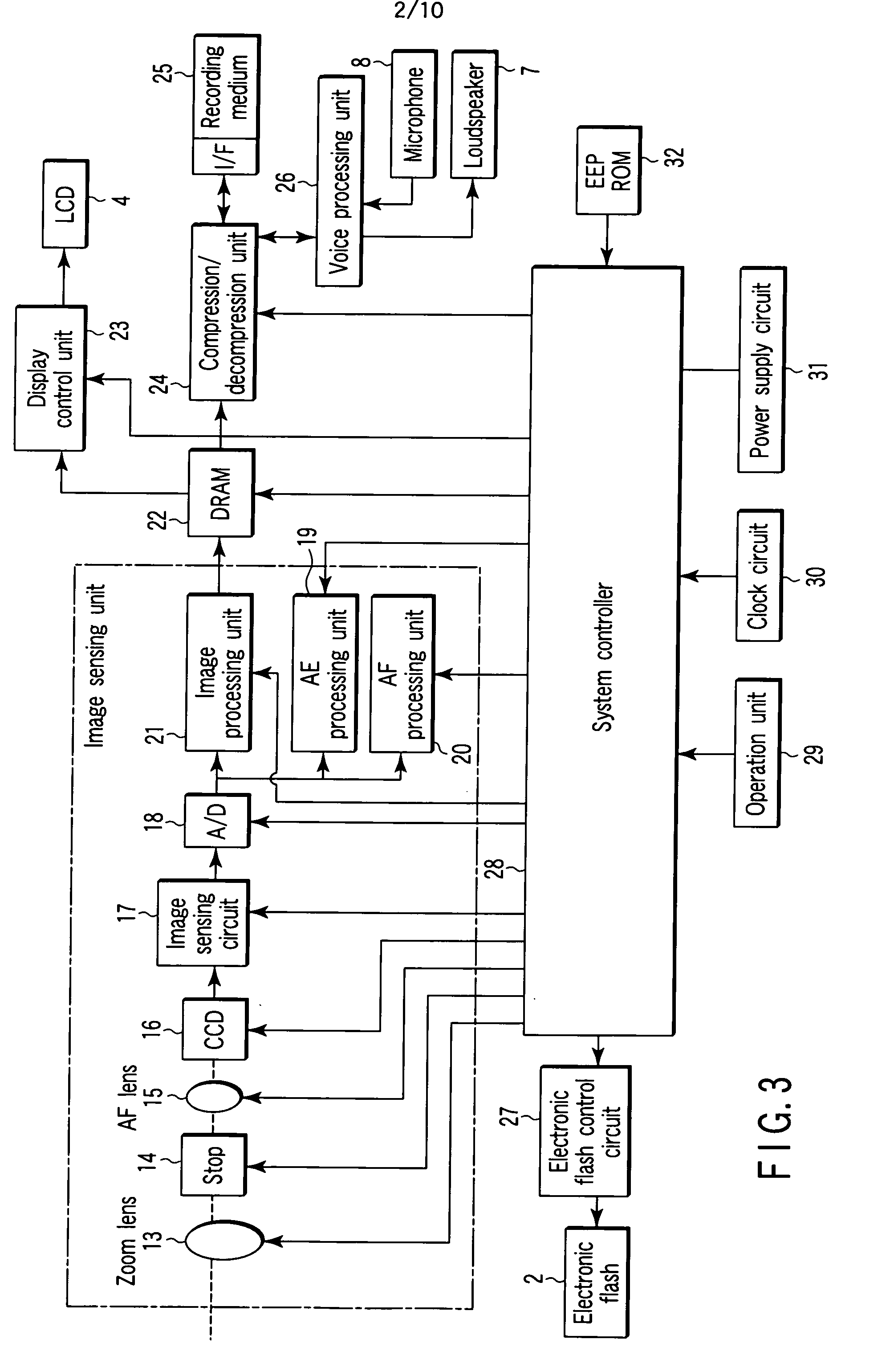
[0030]FIG. 1 is a perspective view showing a camera according to the first embodiment when viewed from the front. This camera is a digital camera which forms an object image on an image sensor through a lens, converts it into an electrical signal, and records the resultant image data of the object image on a recording medium. As shown in FIG. 1, the front surface of the housing of the camera is provided with an aperture portion 1 for allowing object light to enter the camera body and an electronic flash 2 for irradiating an object with...

second embodiment

[0069] A second embodiment of the present invention will be described next.

[0070]FIG. 12 is a view of window transition which shows the flow of scene descriptions in the scene function executed by this camera. The second embodiment differs from the first embodiment in the following points. First, the display element of a first-step explanatory window b′1 is a title instead of a sample image. Second, both the first-step explanatory window b′1 and a second-step explanatory window c′1 are superimposed on a photographing window al displayed as a monitor image to present information necessary for a scene description.

[0071]FIG. 13 is an enlarged view showing the first-step explanatory window b′1 to make it easier to understand. FIG. 14 is an enlarged view showing the second-step explanatory window c′1 to make it easier to understand.

[0072] As shown in FIG. 13, for a skilled user, a title representing the characteristic feature of each scene seems to be sufficient information to be disp...


PUM


Abstract

A camera according an aspect of the invention includes a display unit, a control unit, and a selection unit which selects one of a plurality of scenes prepared in the first explanatory image and the second explanatory image. The control unit displays, as a first explanatory image, a plurality of icons diagrammatically illustrating contents of the scenes as operation guides for the selection unit, and a first sample image serving as a main image representing the contents of the scene corresponding to one of the icons selected by the selection unit, and, as a second explanatory image, a plurality of icons and a descriptive image serving as a main image describing the contents of the scene corresponding to one of the icons selected by the selection unit.

Description

CROSS-REFERENCE TO RELATED APPLICATIONS [0001] This application is based upon and claims the benefit of priority from prior Japanese Patent Application No. 2004-128546, filed Apr. 23, 2004, the entire contents of which are incorporated herein by reference. BACKGROUND OF THE INVENTION [0002] 1. Field of the Invention [0003] The present invention relates to a camera which supports the operation of selecting an optimal photographing condition from a plurality of photo-graphing conditions for each of photographic occasion by efficient procedures. [0004] 2. Description of the Related Art [0005] Photographing conditions including aperture, shutter speed, ISO sensitivity, and the like can be variously set within a predetermined range. Many recent cameras have two operation modes, i.e., manual mode for manually setting these items, and auto mode for automatically setting all the items in accordance with the situation at a given time. [0006] In order to obtain an image as intended, photograp...

Claims


Application Information

Patent Timeline
IPC IPC(8): H04N5/222G03B17/18H04N5/225H04N5/232H04N101/00
CPCH04N5/23293H04N23/631H04N23/633
Inventor WATANABE, SAYURI
Owner WATANABE SAYURI
Learn More