[0021]The following description is presented to enable one of ordinary skill in the art to make and use the invention. Descriptions of specific embodiments and applications are provided only as examples and various modifications will be readily apparent to those skilled in the art. The general principles described herein may be applied to other embodiments and applications without departing from the scope of the invention. Thus, the present invention is not to be limited to the embodiments shown, but is to be accorded the widest scope consistent with the principles and features described herein. For purpose of
clarity, details relating to technical material that is known in the technical fields related to the invention have not been described in detail.
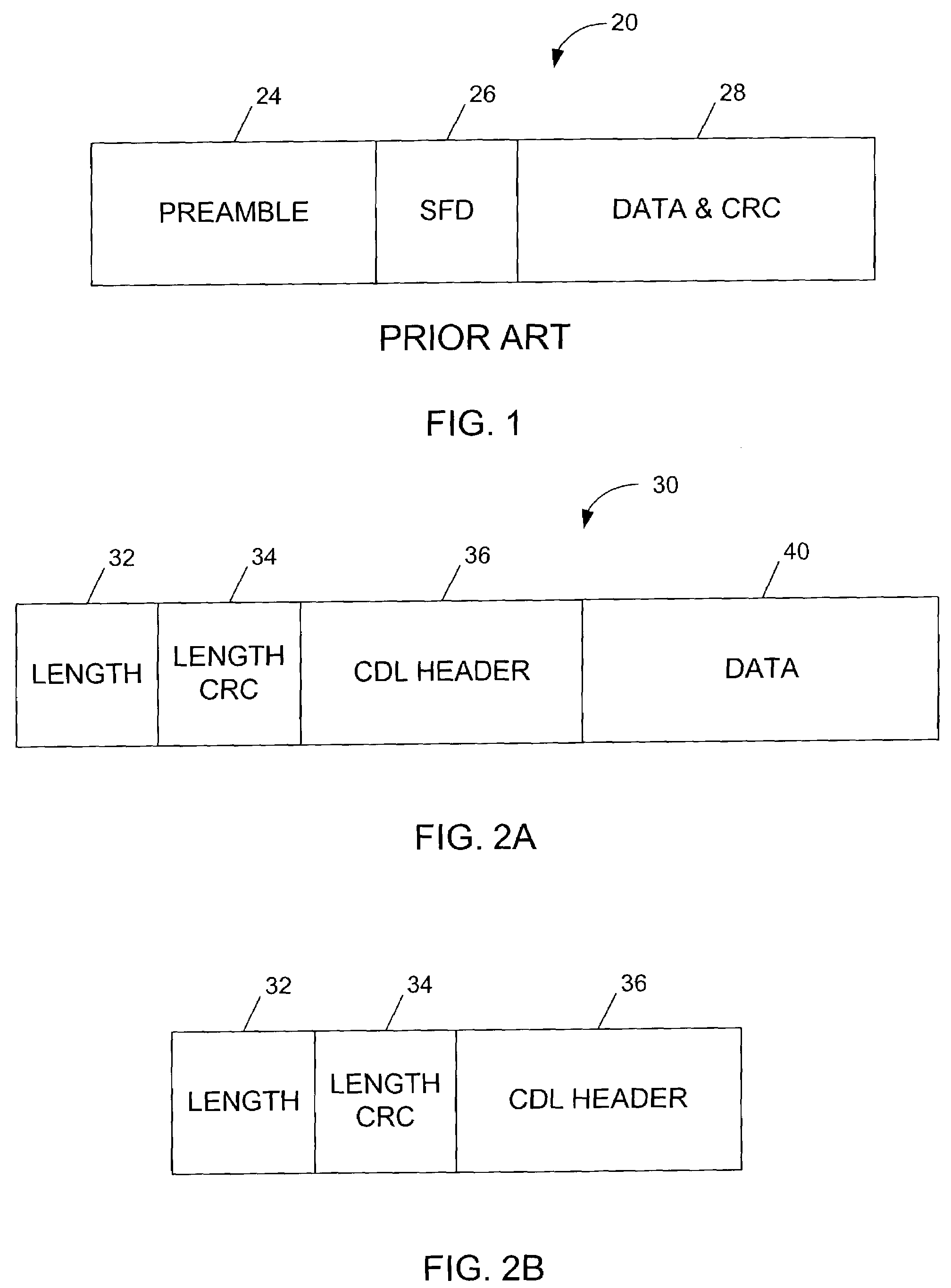
[0013]FIG. 2A illustrates an EFP frame format for Ethernet packets.
[0014]FIG. 2B illustrates an EFP frame format for idle frames.
[0015]FIG. 3 illustrates a format of a Converged
Data Link (CDL) header.
[0019]FIG. 7 is a system
block diagram of a computer system that can be utilized to execute
software of an embodiment of the present invention.
[0020]Corresponding reference characters indicate corresponding parts throughout the several views of the drawings.
[0021]The following description is presented to enable one of ordinary skill in the art to make and use the invention. Descriptions of specific embodiments and applications are provided only as examples and various modifications will be readily apparent to those skilled in the art. The general principles described herein may be applied to other embodiments and applications without departing from the scope of the invention. Thus, the present invention is not to be limited to the embodiments shown, but is to be accorded the widest scope consistent with the principles and features described herein. For purpose of
clarity, details relating to technical material that is known in the technical fields related to the invention have not been described in detail.
[0022]The present invention operates in the context of a data communication network including multiple network elements. The network may be a packet based optical network that uses Ethernet data layer at speeds of 10 Gb / s (or above or below 10 Gb / s), both over high speed point-to-point circuits (i.e., dark
fiber) and over WDM. However, it is to be understood that the system may be used with media types different than those described herein, without departing from the scope of the invention. A
network element may be, for example, a terminal
multiplexer, an add-drop
multiplexer (ADM), an optical crossconnect (OXC), a
signal regenerator,
router, switch, or other optical node interface. The invention described herein may be implemented in dedicated hardware,
microcode,
software, or photonic (optical) logic.
[0023]An efficient framing procedure (EFP) for Ethernet is described herein. EFP is a method of delineating Ethernet packets (i.e.,
byte aligned
variable length packets) for subsequent mapping into byte synchronous paths such as the SONET / SDH and OTN (based on, for example, ITU-T G.975). EFP also provides a set of
adaptation functions for subsequent mapping into byte synchronous paths such as the SONET / SDH and OTN.
[0024]As described in detail below, EFP carries all seven Ethernet
preamble bytes and removes the SFD. EFP is able to carry CDL based Ethernet packets with the removed SOF. EFP adds four bytes; two for length and two for CRC to enable single bit correction and multi-bit detection within the two length bytes. EFP enables 10 Gb / s Ethernet to be mapped into constant bit
stream (e.g., at 9.953 Gb / s) for maximum packet sizes less than 1878 bytes. This also applies to direct mapping over G.975 FEC payload. EFP also enables 10 Gb / s Ethernet to be mapped into OTU2 for maximum packet sizes less than 15177 bytes without requiring any
rate control. Thus, EFP enables use of 10 Gb / s Ethernet in long haul networks where FEC is a requirement. EFP, through its inclusion of CDL (Converged
Data Link) header supports packet-by-packet
multiplexing and OAM&P.
[0025]Referring now to the drawings, and first to FIG. 1, a simplified example of an
Ethernet frame 20 is shown. The frame includes a
preamble 24, start of frame
delimiter (SFD) 26, and a
data field 28 (which includes CRC (Cyclic Redundancy Checks). Standard IEEE 802.3 Ethernet packets typically include the following fields (not shown) after the preamble: destination address,
source address, length or type field,
data field, and frame check sequences.
[0026]FIG. 2A illustrates an example of an EFP encapsulated frame 30. The EFP frame 30 is byte aligned and consists of a Length Header, a CDL Header 36, and an EFP Data area 40. The Length Header includes a 16-
bit length field 32 (supporting packets of size up to 64 k bytes) and a 16-
bit length CRC (LCRC) field 34. The length encompasses the entire frame and the minimum value for length is preferably 11. This minimum value is used to fill the bandwidth when no Ethernet Packets are available or when CDL idle packets are received from a
client interface. A value of zero in the length field identifies an EFP idle frame. Length values from 1 to 10, inclusive, are reserved for future definition. The Length Header is scrambled by exclusive-OR (also known as “modulo 2 addition”) with the hex value B6AB31E0 (which is the maximum transition, minimum sidelobe, Barker-like sequence of length 32).
[0027]The 16-bit LCRC is computed over the 16-
bit length field. It is used for single bit error correction and multi-bit error detection. The LCRC generating polynomial may be, for example:
[0029]x^16 corresponds to the most significant bit; and
The 16-
bit Length is taken to be a polynomial L(x) of degree 15. L(x) is multiplied by x^16 (modulo-2) and divided by G(x). The remainder is a polynomial C(x) of degree 15 or less and is the LCRC. LCRC is transmitted MSB (coefficient of x^15) first.
[0031]Packet delineation is performed using a 2-byte length and 2-byte length CRC. Frame delineation may be performed, for example, using the Length and the LCRC in a Hunt procedure. The Hunt procedure is performed in parallel over eight streams. When a pre-synch state is reached (i.e., a match between length and CRC is found) and is maintained for the next frame, the synch is declared.
[0032]The CDL Header is described in U.S.
patent application Ser. No. 09 / 668,253, filed Sep. 21, 2000, entitled Method and
System for Providing Operations, Administration, and Maintenance Capabilities in Packet Over
Optics Networks, which is incorporated herein by reference in its entirety. The CDL header provides operations, administration, maintenance and provisioning (OAM&P) (or OAM, or any single feature or combination thereof),
multiplexing, and multiple qualities of service in packet over
optics networks. For example, CDL may support general management of optical networks, supervision of unused channels, provisioning of optical paths,
performance monitoring of optical paths, and failure
recovery. CDL also enables multiplexing of multiple logical lower speed circuits across a single optical channel including support for a multi-access form of statistical multiplexing appropriate to ring topologies and support for frame-by-frame multiplexing. It is to be understood that CDL may provide all of the above mentioned functions, only one of these functions, or any combination thereof, without departing from the scope of the invention. CDL Ethernet employs the same PMA and PCS
layers as Ethernet for
signal rates of 100 Mb / s, 1000 Mb / s, and 10 Gb / s. This addresses transport of Ethernet and CDL Ethernet over short reach, intermediate reach, and long reach dark
fiber links.
[0033]CDL is a wrapper around the
link layer packet. The CDL wrapper comprises a self-contained 7 byte CDL header that is prepended to standard Ethernet packets (e.g., IEEE 802.3) by replacing a preamble of the Ethernet packet. When applied to a standard
Ethernet frame (IEEE 802.3), the CDL wrapper substitutes the SFD byte and the preceding six preamble bytes. The Ethernet frame is located after the CDL header, which replaces bytes in the standard Ethernet preamble. It is to understand that although the invention is described herein using an Ethernet packet, other types of packets having a preamble may also be used. Thus, the term “Ethernet packet” or “Ethernet frame” as used herein includes packets or frames formatted according to standards other than IEEE 802.3.
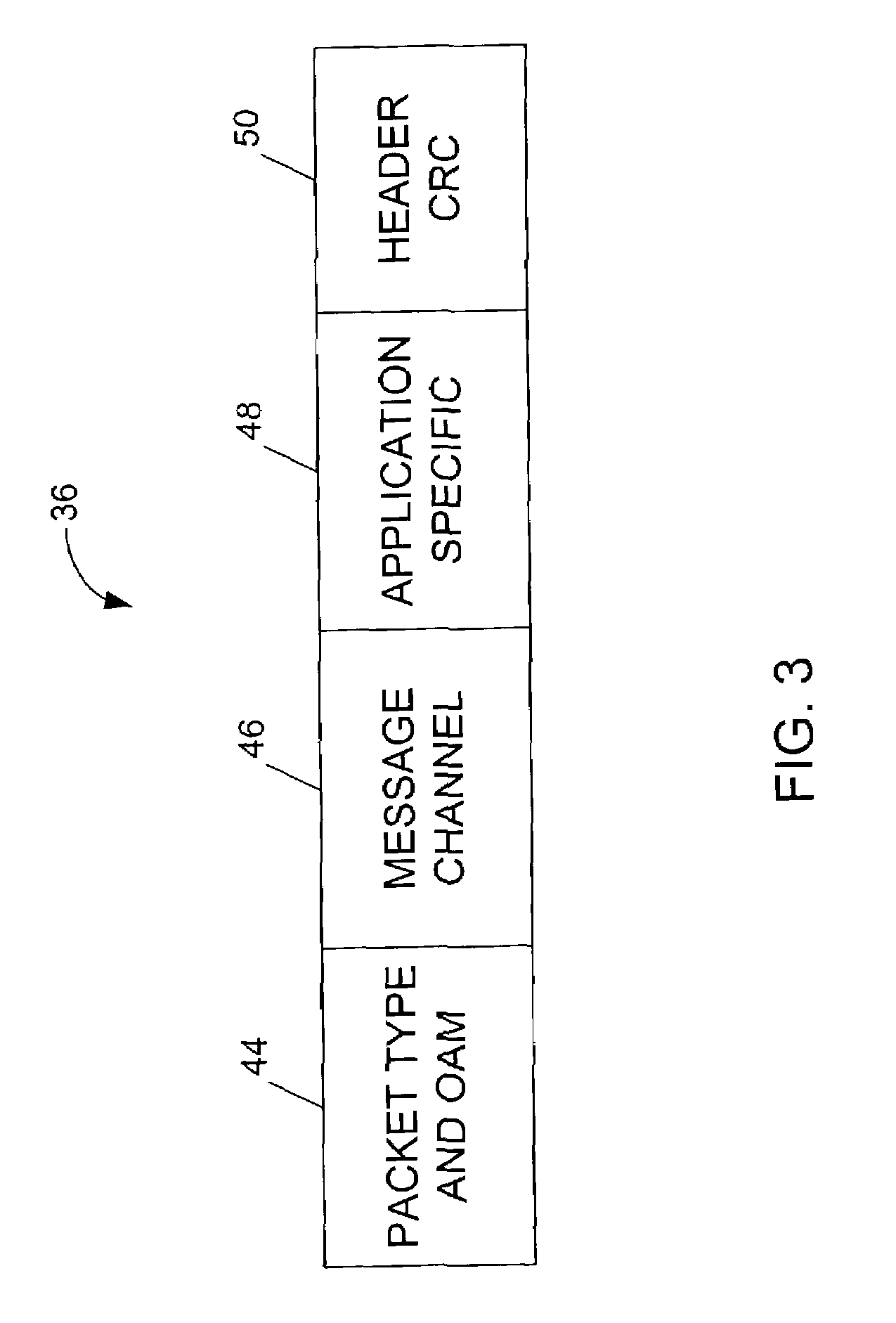
[0034]FIG. 3 illustrates an example of fields within the CDL header. The fields preferably included in the CDL header 36 are:
[0035]
Byte [1]: Packet type and OAM information 44
[0039]The OAM field 44 carries packet type information, error flags, and an
automatic protection switching (APS) subchannel. OAM includes, for example, the following fields:
[0053]The 10 Gb / s EFP sink, upon receiving EFP Idle frame with BDI-E bit set or an OTU2-AIS (
Alarm Indication Signal) defined by the ITU G.709 standard, begins to forward RF SOSs. The EFP source stops forwarding EFP Idle frames with BDI-E set when the RF condition clears (as specified in IEEE 802.3ae Section 46.3.2). The EFP sink stops forwarding RF SOSs if an EFP Idle frame with BDI-E bit clear or an EFP
Client Data frame is received or OTU2-AIS clears (as specified in ITU-T G.709). In addition, an LF and RF indication are propagated to the far end using the same CDL FDI / BDI propagation mechanism.
Automatic protection switching (APS) provides the capability of a
transmission system to detect a failure on a working facility and to switch to a standby facility to recover the traffic, thus, improving overall system availability. The type field identifies whether or not the data and CRC fields are present.
[0046]The message channel 46 provides a communication mechanism between network elements. Messages are hop-by-hop and may be forwarded or routed according to established routing protocols. The message channel 46 allows management communication over the same physical facilities as the user data but without taking any bandwidth from the user data.
[0047]The
application specific (AS) field 48 carries information between end nodes that is forwarded along an
optical path. The
application specific field 48 may include a subinterface identifier to assist in multiplexing packet streams. The
application specific field 48 may also be used to support applications other than multiplexing. For example, the application specific field 48 may be used to facilitate multi-protocol
label switched routing.
[0048]The header CRC 50 is employed for header error protection and covers the CDL header. The CRC is preferably computed over the entire value of the CDL header, including the AS field 48. The CRC may be based on CRC-8 [ITU-T G.432.1]. For example, the CRC header may be an 8-bit sequence that is the remainder of the modulo-2 division by the generator polynomial x^8+x^2+x+1 of the product x^8 multiplied by the content of the CDL header excluding the header CRC. The 48-bit long relevant portion of the CDL header is taken to represent a polynomial of order 47. The coefficients can have the value 0 or 1. The first bit of the header represents the coefficient of the highest order (x^47) term. The polynomial operations are performed modulo-2. The CRC header is preferably recomputed whenever any of the fields in the header are changed and passed transparently whenever the fields of the header do not change.
[0049]It is to be understood that other related or unrelated fields may be included between any of the above fields or the fields may be in a different order without departing from the scope of the invention.
[0050]Referring again to FIG. 2A, the EFP frame includes EFP Data 40. The EFP Data area may be scrambled using a 1+x^43 self-synchronous scrambler. If it is not required to provide security against payload information replicating scrambling word (or its inverse) from a frame synchronous scrambler, such as those used in the SDH RS layer or in an OTN OPUk channel, the Data area may not be scrambled. The content of Data area 40 preferably includes an FCS (Frame Check Sequencer) field for Ethernet packets.
[0051]EFP packet types include EFP Ethernet packet, EFP CDL idle, and EFP idle. The EFP CDL idle is the mapping of a CDL idle packet coming from the client interface that has to be propagated to the far end client. The EFP CDL idle includes the length 32, length CRC 34, and CDL header 36 fields. EFP CDL is used for
fault propagation purposes, as described above. The EFP idle, shown in FIG. 2B, is used to fill the bandwidth when there is nothing to transmit. The EFP idle frame is provided as a filler frame, since one of the requirements for mapping EFP frames into octet synchronous paths is for the capacity of such paths to be not less than the capacity required by the Ethernet
stream. The EFP idle frame may also be used to enable frequency tolerance compensation. EFP Idle Frames have a length of 11 and are identified by 0 in the Length field 32.
[0052]Defect Handling is provided by the CDL header. A
Client Signal Fail condition (e.g., loss of signal) is handled by the EFP source generating a
stream of all EFP Idle frames and setting the FDI-H bit in the CDL header (see previous description of defect indication bytes in CDL header). The 10 Gb / s EFP sink, on receiving the EFP Idle frame with FDI-H bit set, begins to forward the LF SOS (Local Fault Sequence Ordered Set), as specified, for example, in IEEE 802.3ae 10 Gb / s Ethernet
Task Force, Section 46.3.2. The EFP sink stops to forward LF SOS if an EFP Idle frame with FDI-H bit clear or an EFP
Client Data frame is received. A 10 Gb / s EFP source, upon receiving RF (Remote Fault) SOS and determining the RF condition, begins to generate a stream of all EFP Idle frames. The BDI-E bit the CDL Header is then set.
[0053]The 10 Gb / s EFP sink, upon receiving EFP Idle frame with BDI-E bit set or an OTU2-AIS (
Alarm Indication Signal) defined by the ITU G.709 standard, begins to forward RF SOSs. The EFP source stops forwarding EFP Idle frames with BDI-E set when the RF condition clears (as specified in IEEE 802.3ae Section 46.3.2). The EFP sink stops forwarding RF SOSs if an EFP Idle frame with BDI-E bit clear or an EFP
Client Data frame is received or OTU2-AIS clears (as specified in ITU-T G.709). In addition, an LF and RF indication are propagated to the far end using the same CDL FDI / BDI propagation mechanism.
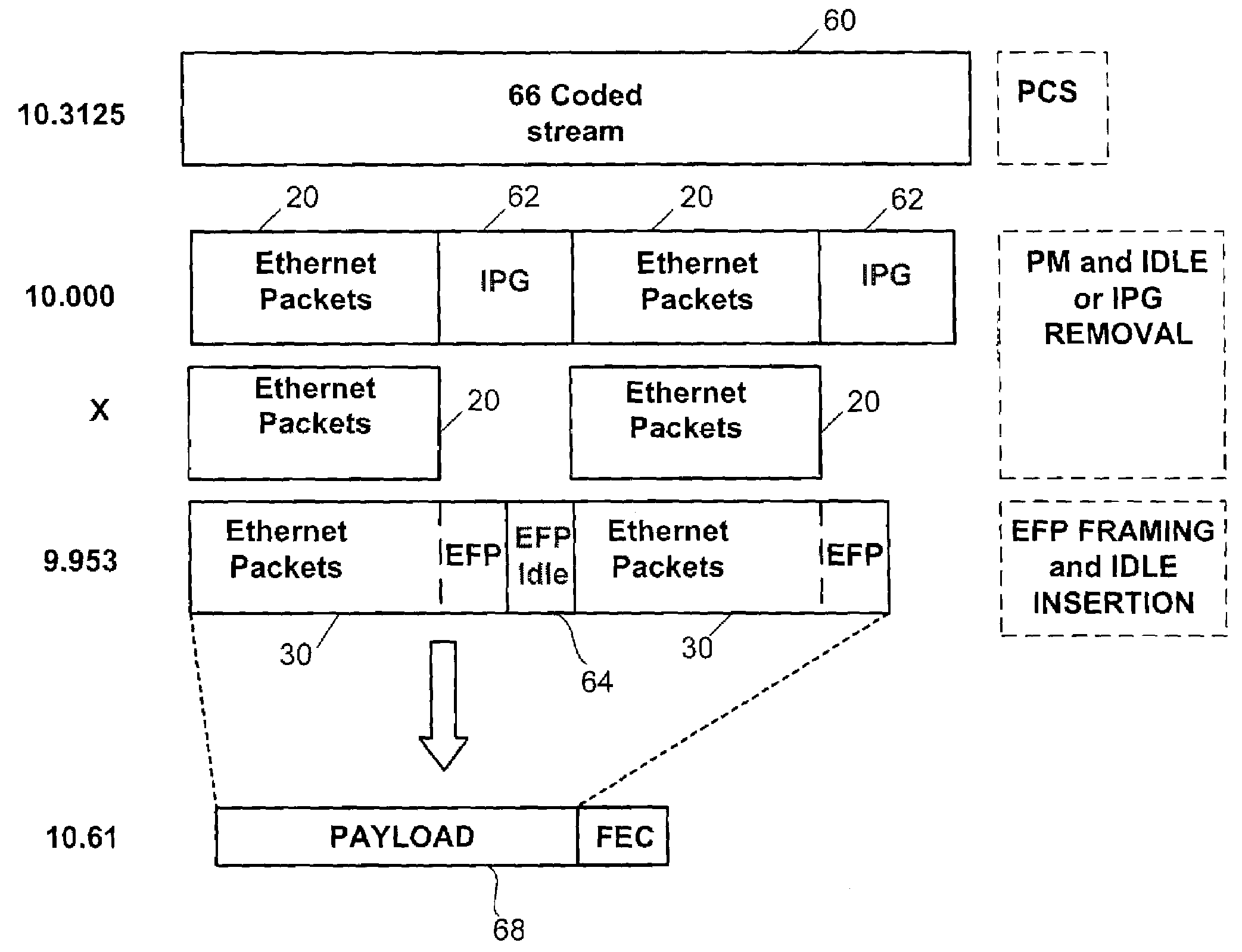
[0054]When Ethernet traffic is sent to a SONET / SDH network, the Ethernet frames are first mapped into a frame with an appropriate structure and then mapped to the SONET (or other appropriate payload envelope). The following describes how EFP may be used to transport 10 GE interface over a WDM system that uses FEC to improve optical system performance. In one embodiment, the system provides rate
adaptation between a 10 GE client interface (10.3125 Gb / s) and a G.975 FEC payload rate (9.9532 / s).
[0055]FIG. 4 is a high level
block diagram illustrating rate
adaptation in the transmitting direction. The 10.3125 Gb / s signal is converted to an XGMII (10G Medium Independent Interface) through a standard Ethernet PCS (Physical Coding Sub-layer) block 60. The IPGs (InterPacket Gaps) 62 are then removed and the EFP mapping procedure (described above) is used to build a constant bit stream running at 9.9532 that will be sent to FEC payload 68 for encoding. EFP framing is performed and EFP idle frames 64 are inserted as required. The signal may be mapped into an FEC frame of a long-haul DWDM transport platform, such as ONS 15808, available from Cisco Systems, Inc. of San Jose, Calif., for example. To maximize the available bandwidth, the
insertion of overhead bytes is preferably limited to three (the minimum set required for alignment purposes).
[0056]FIG. 5 illustrates receiving flow rate adaptation. The EFP frames 30 are preferably detected using a parallel Hunt
algorithm to minimize the time for EFP alignment. The EFP overhead is then removed and the IPG and the SFD are reinserted. After the EFP de-mapping process is complete the Ethernet packets 20 are sent to PCS
coding block 60 and IPG 62 are inserted as required. If the client network is based on standard Ethernet (IEEE 802.3), the packet preamble bytes are replaced by CDL preamble. If the client network includes CDL preamble capability, the preamble bytes are passed through.
[0057]FIG. 6 is a
flowchart illustrating the flow rate adaptation described above along with two additional methods. At step 70, PCS block decoding is performed. Packet buffer for length calculation is performed at step 72. Next, idle removal and EFP mapping are performed (step 74). At step 78, a 9.953 Gb / s constant bit stream signal is built to be mapped into a G.975 FEC frame (as previously described). As shown at step 76, the EFP packet may also be mapped into a SONET / SDH payload (OC-192 / STM-64
transceiver). Another option is to build an EFP stream of 9.995 Gb / s (OPU2 payload rate) so that the EFP stream can be directly mapped into a ITU-T G.709 frame (step 80).
[0058]The available bandwidth for Ethernet packet transport in the three methods of FIG. 6 (steps 76, 78, and 80) is as follows:
[0065]SONET / SDHG.975 FECOTNPayload rate9.549.9539.999(Gb / s)Max packet size200180019000supported (12 IPG)Max packet size154114000135000supported (70 IPG)
[0065]SONET / SDHG.975 FECOTNPayload rate9.549.9539.999(Gb / s)Max packet size200180019000supported (12 IPG)Max packet size154114000135000supported (70 IPG)
[0062]The following is an example of a calculation of the maximum packet size (L) that can be carried using EFP.
From the above equation, the maximum packet size (L) that can be carried by the SONET OC192 signal using EFP is calculated as approximately 19000 bytes for OPU mapping, 1800 for G.975 FEC payload (9.953 Gb / s) and 200 for OC-192 / STM16 mapping. Precise values depend on the
clock accuracy.
[0064]The following table provides examples of calculations for maximum packet size (L) for payload rates (WDMPayload_rate) of 9.54 Gb / s, 9.953 Gb / s, and 9.999. Gb / s with an IPG of 12 and 70:
[0065]SONET / SDHG.975 FECOTNPayload rate9.549.9539.999(Gb / s)Max packet size200180019000supported (12 IPG)Max packet size154114000135000supported (70 IPG)
[0066]The following is a bandwidth performance calculation example assuming a constant flow of maximum Ethernet packet length (1518 bytes) with a minimum average IPG of 10.5. This average IPG takes into account the RS IPG removal /
insertion and
frequency compensation. With an available data bandwidth of 9.95328 Gbs, the maximum continuous stream packet length is calculated as follows:

