Network topology configuring method and node

a topology and network technology, applied in the field of network topology configuring method and node, can solve the problems of nodes needing time and the network load is increased

Inactive Publication Date: 2005-10-27
GOOGLE LLC
View PDF16 Cites 85 Cited by
  • Summary
  • Abstract
  • Description
  • Claims
  • Application Information

AI Technical Summary

Benefits of technology

[0016] The present invention has been made in view of the above problems, and has an object of providing a network topology configuring method in which a new entry node joins a network by a predetermined algorithm, whereby the new entry node can quickly find the positional relationships between nodes in the network, and an occurrence of a node failure, disengagement or the like in the network only locally affects the network, and a node used in the network topology configuring method.

Problems solved by technology

The conventional network topology configuring method, however, has a problem in that the new entry node 105 has difficulty in quickly finding the positional relationships between the nodes in the network it has entered, and takes time to obtain network topology configuration information on each node constituting a part of the network.
This causes the problem in that the network load is increased, and the nodes need time to update network topology configuration information.

Method used


Image

  • Network topology configuring method and node
  • Network topology configuring method and node
  • Network topology configuring method and node

Examples


first embodiment

of the Invention

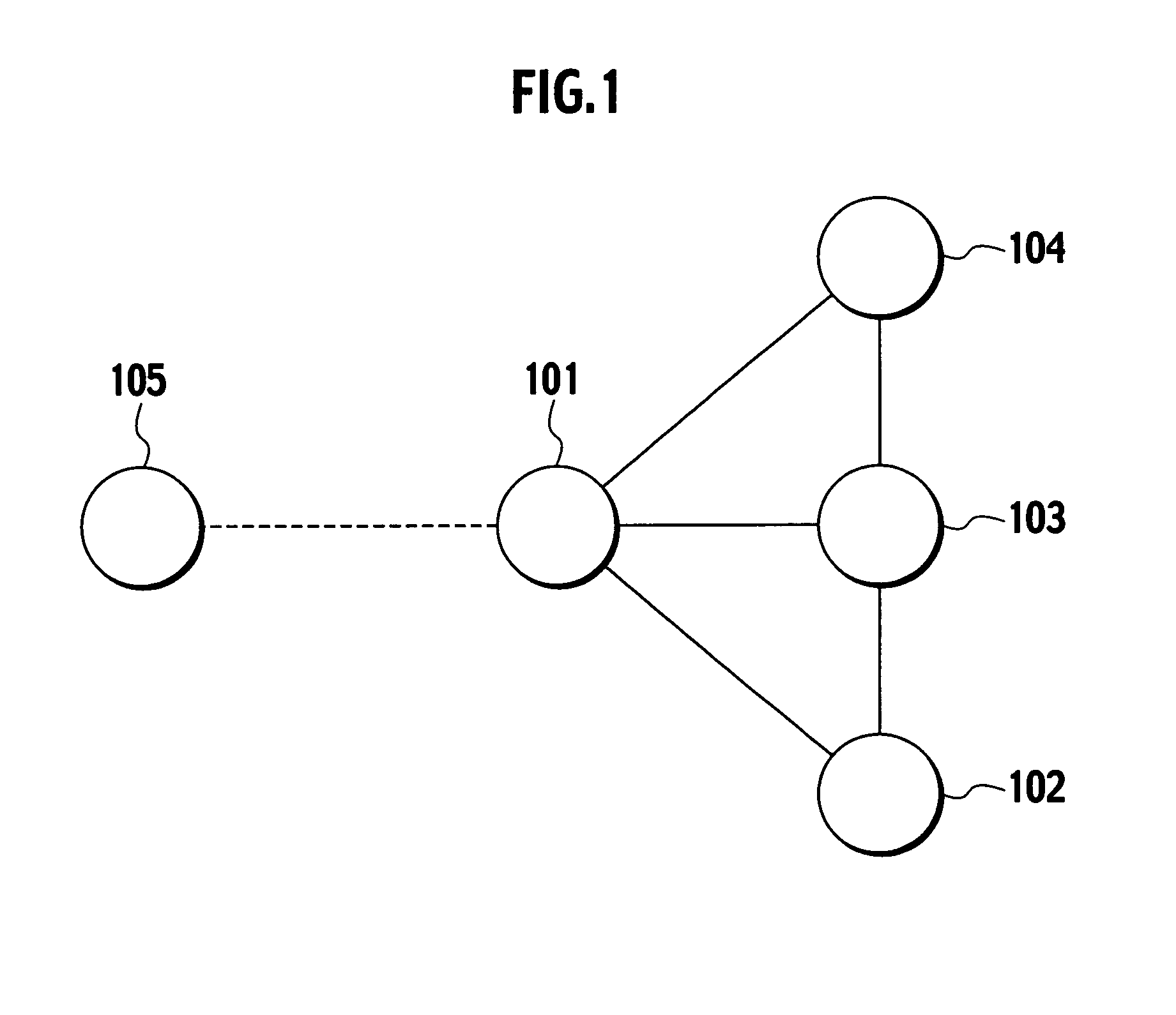
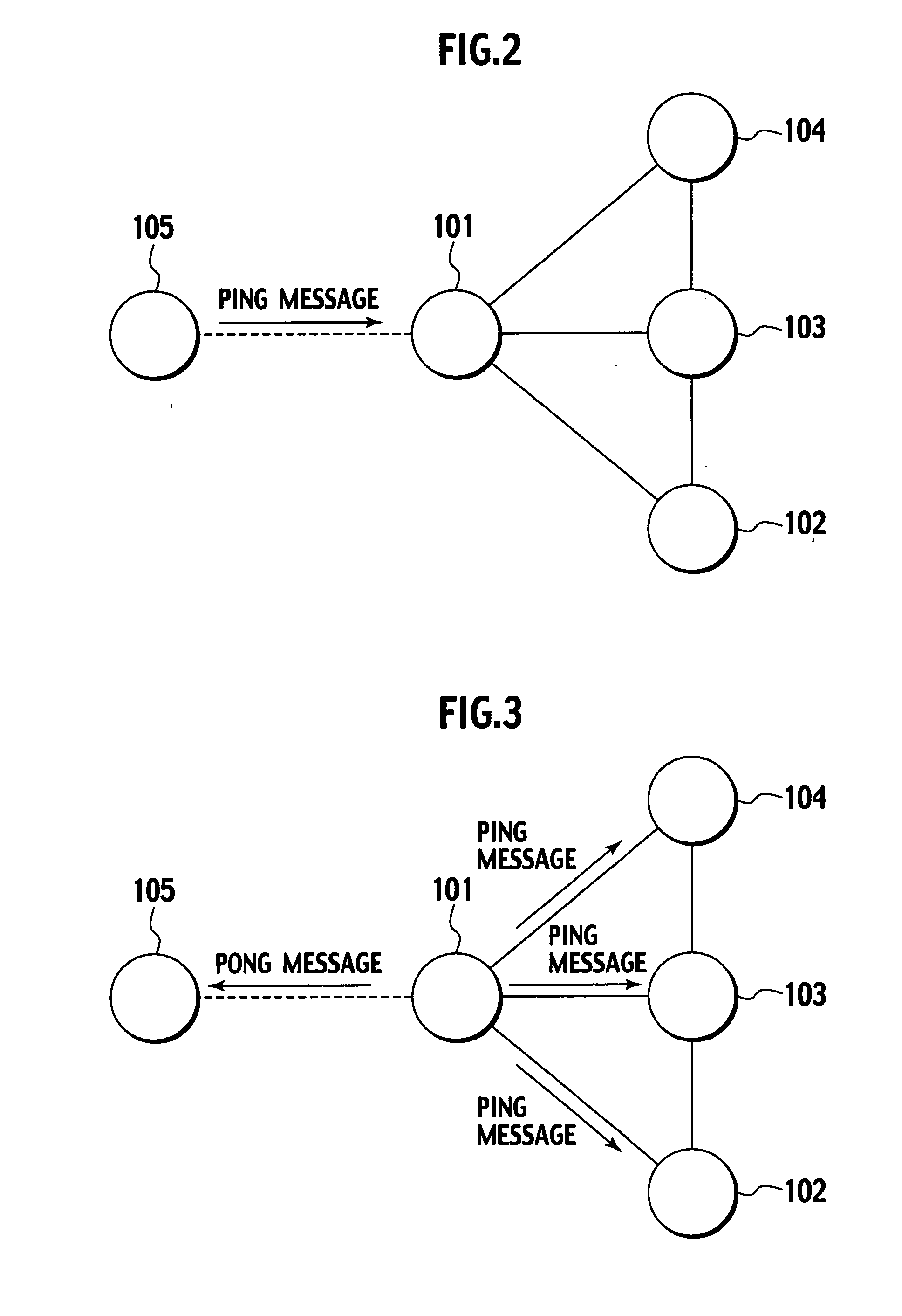
[0041] With reference to FIGS. 6 to 15, a first embodiment of the present invention will be described below. This embodiment will be described with an example in which, as shown in FIG. 6, a new entry node 105 newly joins a ring network constituted by a plurality of nodes 101 to 103 and so on. In this embodiment, as shown in FIG. 7, the new entry node 105 is inserted between the node 101 and the node 102 in the ring network.

[0042] In this embodiment, as shown in FIGS. 6 and 7, the hash value of the node 101 is “Ni,” the hash value of the node 102 is “Ni+1,” the hash value of the node 103 is “Ni−1,” and the hash value of the node 105 is “N”. The hash values of the nodes 101, 102, 103 and 105 are generated from identification information on the nodes 101, 102, 103 and 105 (e.g., universal unique identifiers (UUIDs) or the like).

[0043] First, referring to FIG. 8, the functions of the new entry node 105 will be described. As shown in FIG. 8, the new entry node 105 incl...

second embodiment

of the Invention

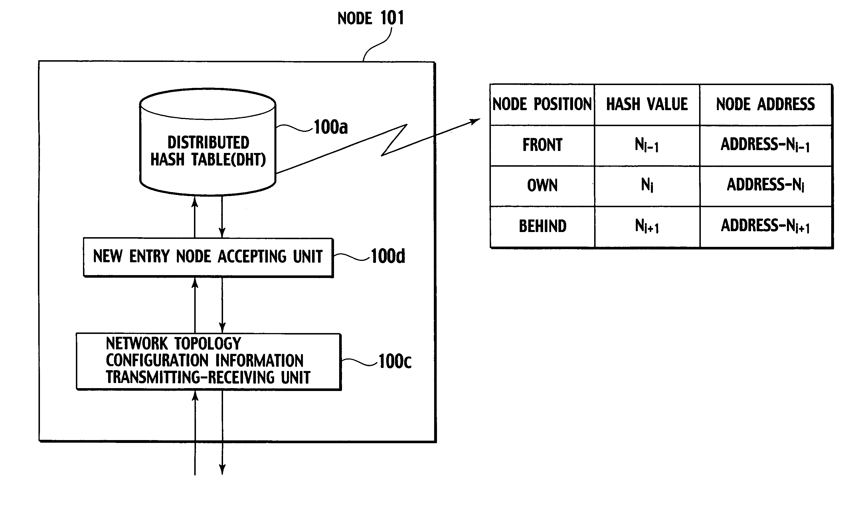
[0109] In a second embodiment of the present invention, distributed hash tables 100a in a new entry node 105 and a node 101 are configured to manage the hash values of all the nodes constituting a ring network, generated from identification information on the nodes.

[0110] Specifically, as shown in FIG. 15, each distributed hash table 100a is configured to manage hash values and node addresses associated with node positions from “1” indicating the node position of a node having a minimum hash value to “n” indicating the node position of a node having a maximum hash value.

[0111] That is, the distributed hash table 100a is configured to manage network topology configuration information showing the topology of all the nodes constituting the ring network.

[0112] A new entry node accepting unit 100d of the node101 according to this embodiment is configured to calculate the insertion position of the new entry node 105 in the ring network, based on the hash value “N” of th...


PUM


Abstract

A node includes a manager configured to manage the hash value of the node and the hash values of adjacent nodes, and a calculator configured to calculate an insertion position of a new entry node in a ring network, based on the hash value of the new entry node, the hash value of the node and the hash values of the adjacent nodes.

Description

CROSS REFERENCE TO RELATED APPLICATION [0001] This application is based upon and claims the benefit of priority from the prior Japanese Patent Application No. P2004-4663, filed on Jan. 9, 2004; the entire contents of which are incorporated herein by reference. BACKGROUND OF THE INVENTION [0002] 1. Field of the Invention [0003] The present invention relates to a method of configuring a network topology when a new entry node joins a ring network which is constituted by a plurality of nodes. The present invention also relates to a node constituting a part of a ring network which is constituted by a plurality of nodes, and a node newly joining the ring network. [0004] 2. Description of the Related Art [0005] Referring to FIGS. 1 to 5, a conventional network topology configuring method (a method used in the “Gnutella”) will be described. In particular, operations for a node 105 to newly join a network including nodes 101 to 104 will be described. [0006] First, as shown in FIG. 1, the nod...

Claims


Application Information

Patent Timeline
Patent Type & Authority Applications(United States)
IPC IPC(8): H04L12/24H04L12/42H04L12/423H04L29/06H04L29/08H04L29/12
CPCH04L29/06H04L29/12009H04L29/12207H04L29/12783H04L41/0806H04L69/329H04L61/20H04L61/35H04L67/104H04L67/1065H04L67/1046H04L41/12H04L61/50H04L61/00A45F5/00A45F2005/006A45F2200/0516H04L9/40
Inventor WAN, HAOYIISHIKAWA, NORIHIROSUMINO, HIROMITSUKATO, TAKESHIOMATA, EIJI
Owner GOOGLE LLC
Why Eureka
Try Eureka