Automatic and manual wall switch device

a wall switch and automatic technology, applied in instruments, horology, transportation and packaging, etc., can solve the problems of not having the look or feel of a conventional wall switch, prior art electrical timers and devices are not easy to use or user friendly

Inactive Publication Date: 2005-11-03
MORRISON RANDALL L +1
View PDF13 Cites 38 Cited by
  • Summary
  • Abstract
  • Description
  • Claims
  • Application Information

AI Technical Summary

Benefits of technology

[0004] In accordance with the present invention, an electrical wall switch device for automatically and manually turning on and off an electrical load has a control surface occupying a compact predefined area that includes a manual load control switch occupying a first portion of the predefined area for receiving manual inputs for turning on and off the electrical load and a time display for displaying time of day, a load on time and a load off time, said time display occupying a second portion of the predefined area, wherein the first portion of the predefined area appears larger than the second portion of the predefined area.
[0005] In accordance with the present invention, a simple to program electrical wall switch device for automatically and manually turning on and off an electrical load comprises a time display for displaying time of day, a load turn on time and a load turn off time. The switch further comprises a manual load control switch for receiving manual inputs for turning on and off the electrical load, a display control switch containing three positions, a first of three positions for causing display of the load turn on time on said time di

Problems solved by technology

However, these devices are not easy to use or user friendly and do not have the look or feel of a co

Method used


Image

  • Automatic and manual wall switch device
  • Automatic and manual wall switch device
  • Automatic and manual wall switch device

Examples


Embodiment Construction

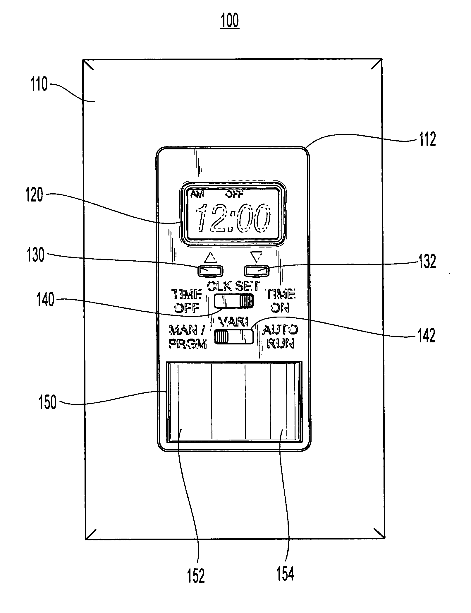
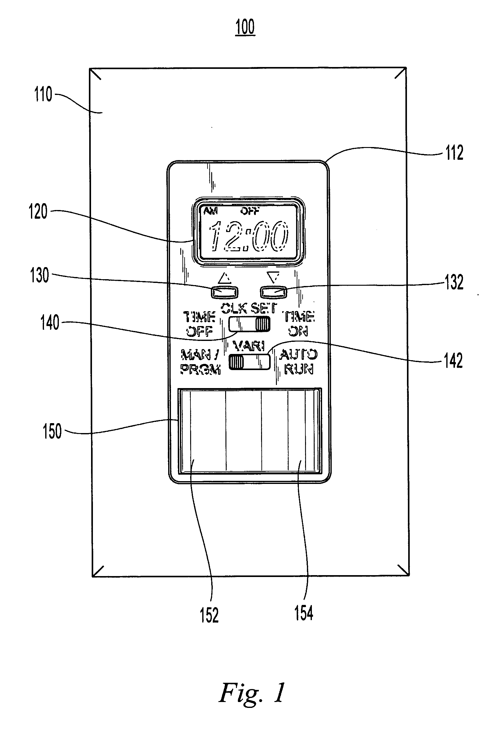
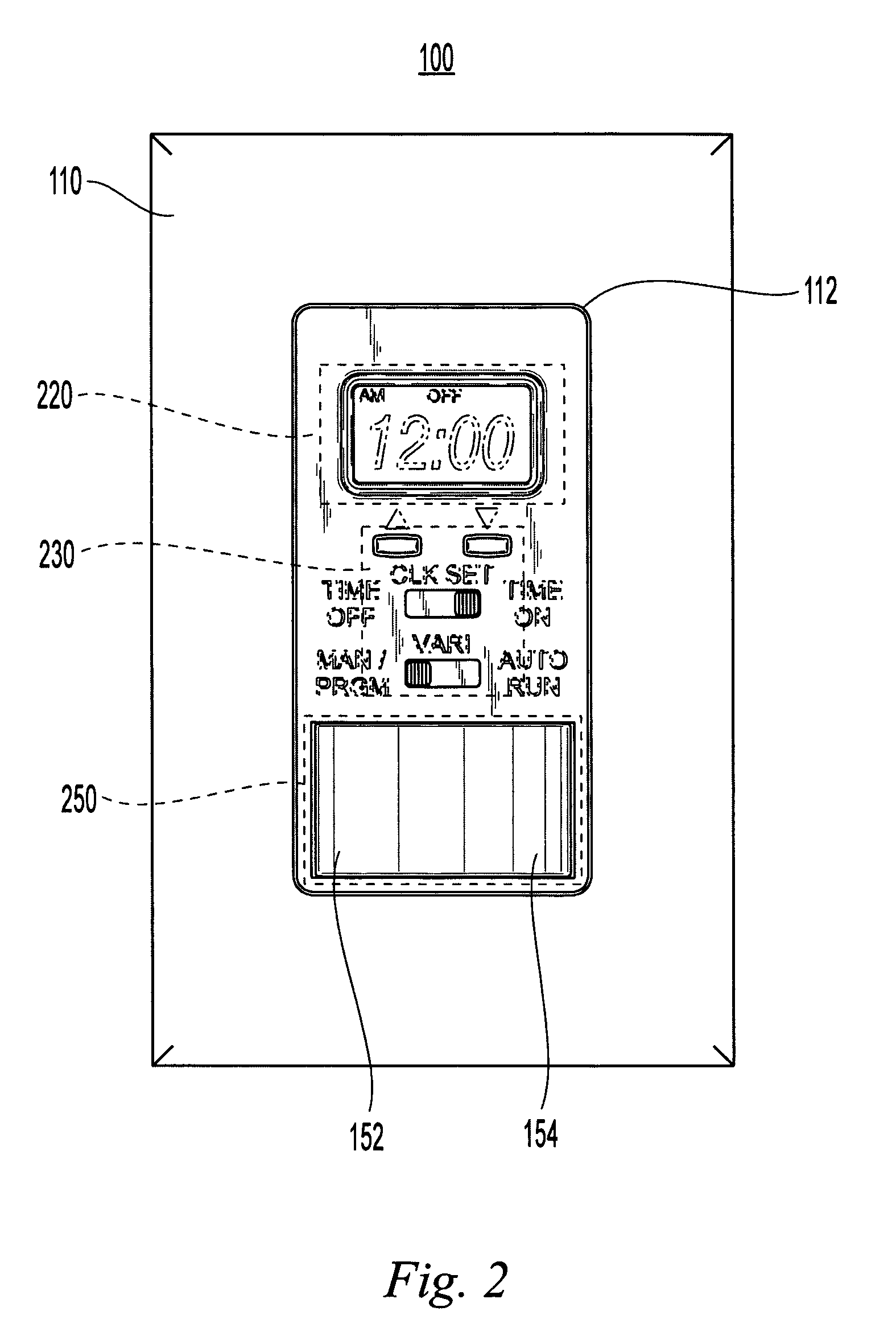
[0018]FIG. 1 shows the appearance of a preferred embodiment of the invention 100. A single gang DECORA style switch plate 110 has an opening 112 defining a compact predefined area for a control surface. The predefined area measures substantially one and one half inches by two and six tenths inches. The control surface of the electrical wall switch of the present invention occupies the predefined opening 112 and has a LCD display 120, which may include a backlight for viewing in the dark, an increment switch 130 for incrementing time settings and a decrement switch 132 for decrementing time settings. Further included is a three positing side switch 140 which functions as a display control for controlling setting of a load turn on time, time of day or a load turn off time dependent upon the position of the three position switch. Further included is a mode switch 142 for setting the operation mode of the wall switch. The operating modes include manual operation or automatic operation b...


PUM


Abstract

An electrical wall switch for turning ON and OFF electrical loads has automatic and manual modes. The wall switch has a display for showing time of day and ON and OFF times. The operation of control switches and their relative placement simplifies setting and using the wall switch. The wall switch includes surge suppression for protection.

Description

FIELD OF THE INVENTION [0001] The invention relates to the area of electrical wall mounted switches for switching on and off electrical loads. BACKGROUND OF THE INVENTION [0002] Electric timers and switches are used in households, businesses and institutions to automatically operate electric appliances, lighting and other electrical devices. One type of electrical timer is used as a substitute for a conventional electric wall switch. This type of electric timer replaces a conventional wall switch with a timer that has an ability to automatically operate whatever had been previously operated by the wall switch. Another type of electric timer has the ability to automatically operate an intended light or appliance while providing the function of a conventional wall switch “ON” and “OFF” operation by an integrated manual override switch built into the timer. [0003] However, these devices are not easy to use or user friendly and do not have the look or feel of a conventional wall switch....

Claims


Application Information

Patent Timeline
IPC IPC(8): B60L1/00G04G15/00H01H43/00
CPCH01H43/00G04G15/00
Inventor MORRISON, RANDALL L.FALLON, KIM P.
Owner MORRISON RANDALL L
Why Eureka
Try Eureka