LED lighting device

a technology of led lighting and lighting devices, which is applied in the direction of lighting support devices, semiconductor devices for light sources, lighting and heating apparatus, etc., to achieve the effect of reducing wiring and/or circuit connections, compact area, and small overall area of lighting devices

Active Publication Date: 2018-12-18
LUMILEDS HLDG BV
View PDF14 Cites 0 Cited by
  • Summary
  • Abstract
  • Description
  • Claims
  • Application Information

AI Technical Summary

Benefits of technology

[0017]A lighting device according to an embodiment may allow for a smaller overall area of a lighting device, as well as a more compact area from which light is output, when compared to a conventional LED lighting device. A lighting device as herein described also allows for reduced wiring and / or circuit connections as well as a reduced overall wiring complexity of the lighting device.

Problems solved by technology

Serially connected LED modules require a larger voltage for correct operation than LED modules connected in parallel, which may be undesirable.
Typically, LED modules connected in parallel disadvantageously comprise a return line positioned between the two LED modules.

Method used


Image

  • LED lighting device
  • LED lighting device
  • LED lighting device

Examples


Embodiment Construction

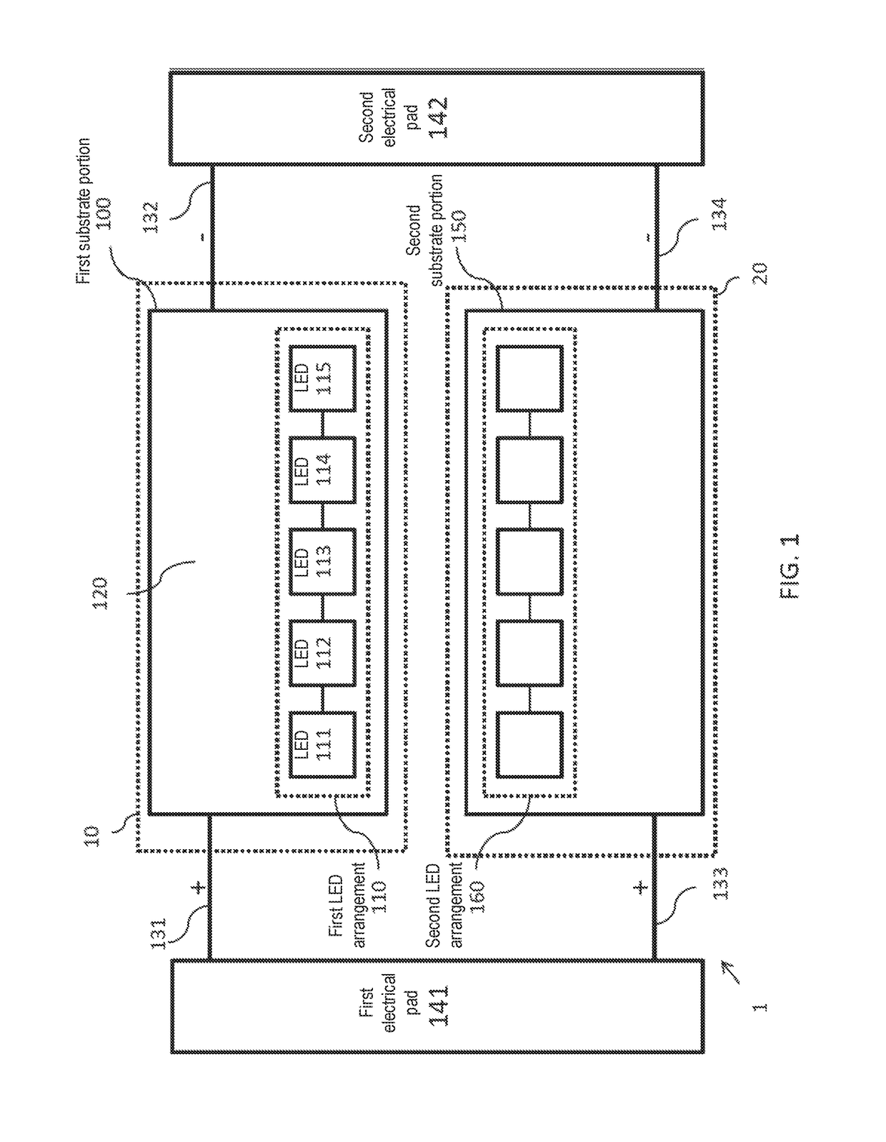
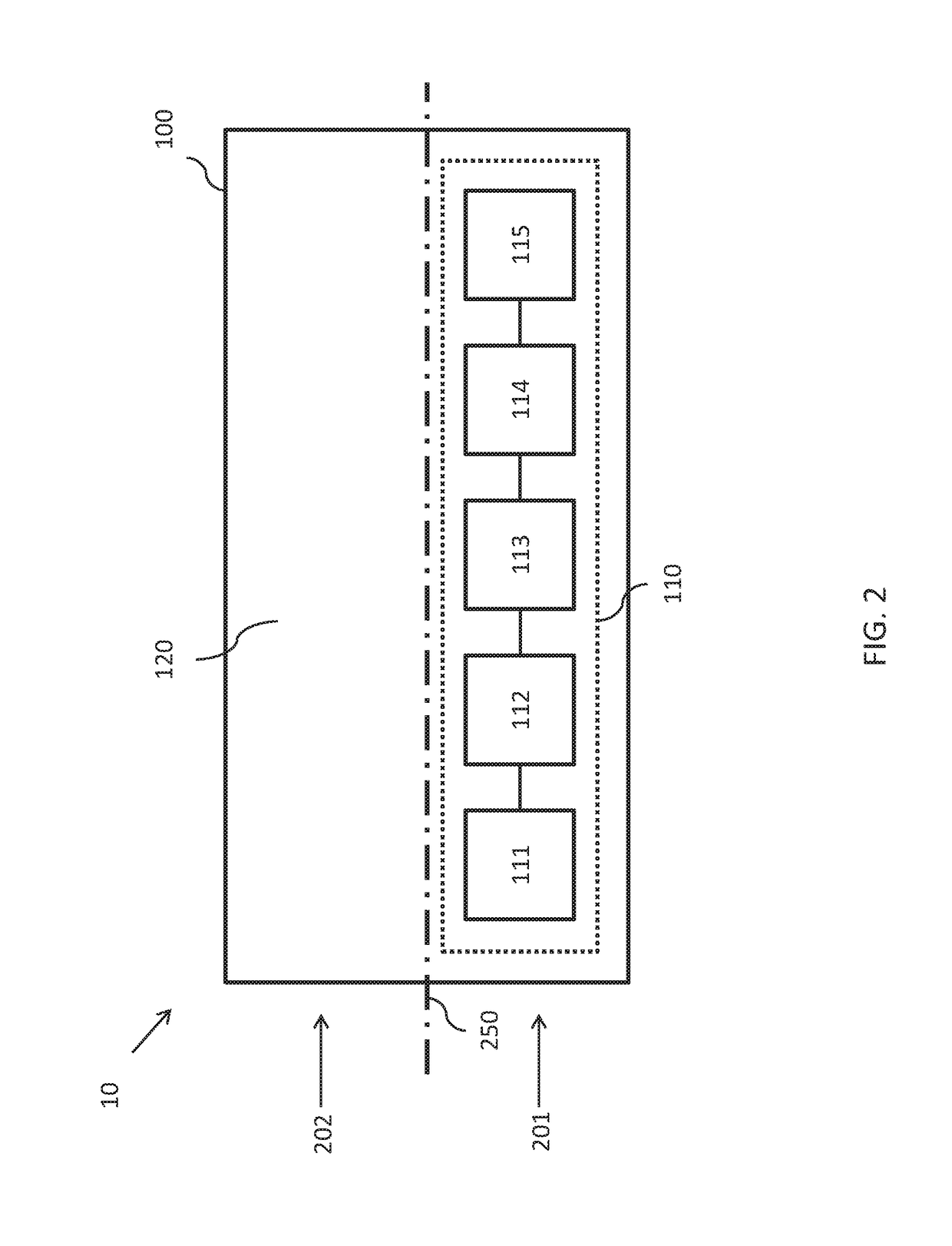
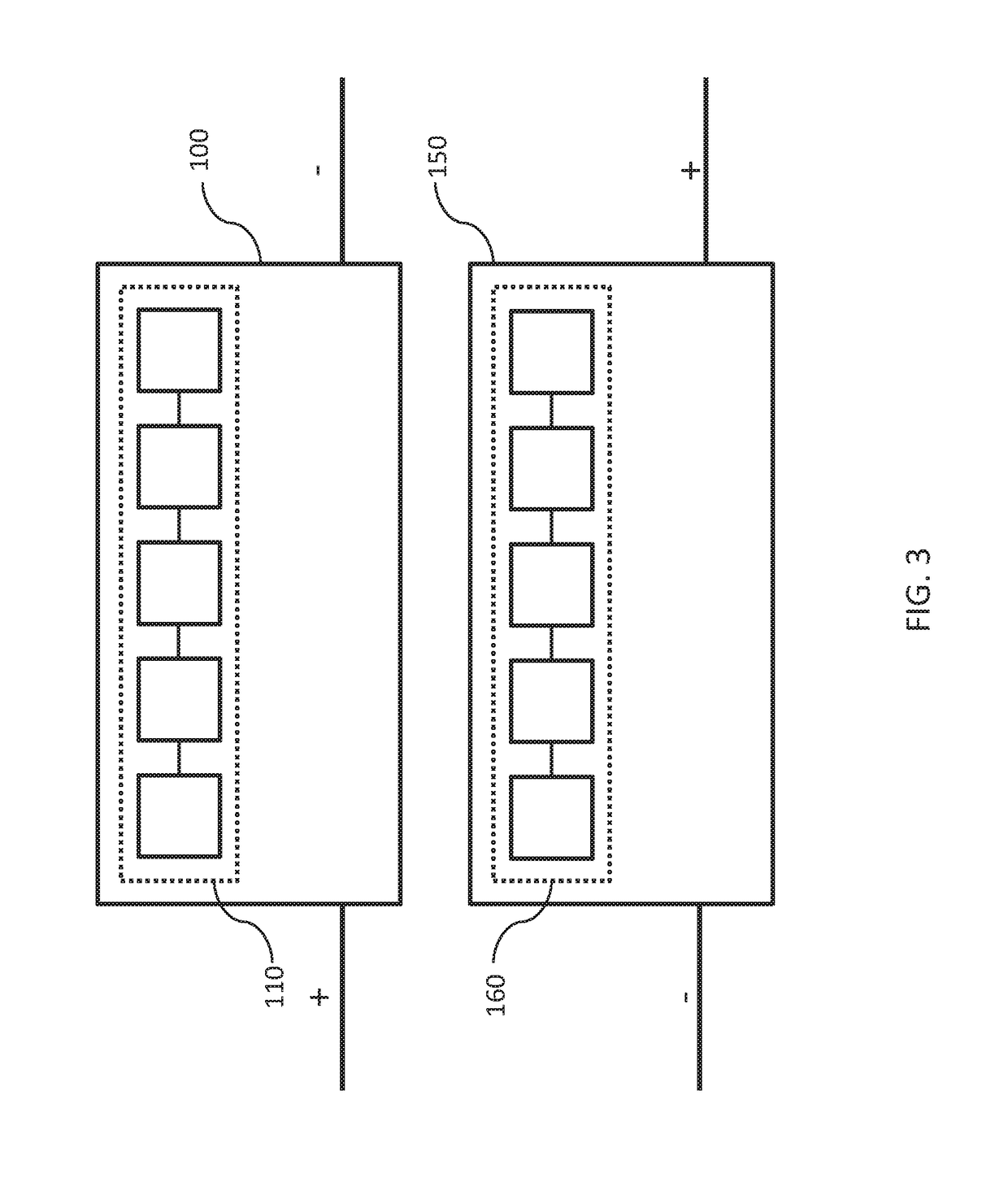
[0050]The invention provides an LED lighting device comprising first and second LED arrangements. Each LED arrangement is positioned on a respective substrate portion so as to form a respective LED module, where each LED arrangement is positioned on its substrate portion so as to be substantially within a single side of a substrate portion surface. The LED modules are arranged such that the first and second LED arrangements are positioned to run alongside one another, such that the positive pole (e.g. the anode) of each LED arrangement is positioned at a first end and the negative pole (e.g. the cathode) of each LED arrangement is positioned a same second end.

[0051]A lighting device 1 according to an embodiment may be readily described with reference to FIGS. 1-5. The lighting device 1 comprises a first LED module 10 having a first substrate portion 100 and a second LED module 20 having a second substrate portion 150. The first LED module comprises a first LED arrangement 110 mounte...


PUM


Abstract

The invention provides an LED lighting device comprising first and second LED arrangements. Each LED arrangement is positioned on a respective substrate portion so as to form a respective LED module, where each LED arrangement is positioned on its substrate portion so as to be substantially within a single side of a substrate portions surface. The LED modules are arranged such that the first and second LED arrangements are positioned to run alongside one another, such that the positive pole (e.g. the anode) of each LED arrangement is positioned at a same first end and the negative pole (e.g. the cathode) of each LED arrangement is positioned a same second end.

Description

CROSS-REFERENCE TO RELATED APPLICATIONS[0001]The present application is a § 371 application of International Application No. PCT / EP2016 / 064849 filed on Jun. 27, 2016 and titled “AN LED LIGHTING DEVICE,” which claims the benefit of European Patent Application No. 15174948.8 filed on Jul. 2, 2015. International Application No. PCT / EP2016 / 064849 and European Patent Application No. 15174948.8 are incorporated herein.FIELD OF THE INVENTION[0002]This invention relates to the field of LED lighting devices and more specifically to the field of LED lighting devices comprising a plurality of LED modules.BACKGROUND OF THE INVENTION[0003]There has been a growing trend toward LED lighting devices, as light emitting diodes (LEDs) are known to have an improved power efficiency and light output over typical halogen light sources.[0004]LED lighting devices may comprise more than one LED module, each module having an arrangement of LEDs positioned toward a single, first side of a respective ceramic c...

Claims


Application Information

Patent Timeline
Patent Type & Authority Patents(United States)
IPC IPC(8): H05B33/08H01L27/15F21V29/70F21V23/02F21V21/00H01L25/07H01L33/60H05K1/14H01L25/075H05K1/02H01L33/62H05B44/00F21Y103/10F21Y115/10
CPCH05B33/0806F21V23/023F21V29/70H01L25/0753H01L27/156H01L33/60H05K1/142H05K2201/10106F21Y2103/10F21Y2115/10H01L33/62H05K1/0209H05K2201/09781H05B45/30
Inventor HENNINGER, GEORG FRIEDRICH ALFONS
Owner LUMILEDS HLDG BV
Why Eureka
Try Eureka