
Automotive outside rearview mirror system having optically similar left and right side mirrors

a technology of rearview mirror and mirror, which is applied in the field of automotive mirrors, can solve the problems of reducing the viewing angle, narrow and relatively useless field of view, and affecting the judgment of both the distance and speed of the vehicle seen in the mirror, and achieves the effect of reducing the distance and speed of the vehicl

Inactive Publication Date: 2005-11-10
PLATZER GEORGE E JR
View PDF99 Cites 101 Cited by
  • Summary
  • Abstract
  • Description
  • Claims
  • Application Information

AI Technical Summary

Benefits of technology

[0009] An object of this invention is to provide a passenger's side outside rearview mirror that provides the driver with the capability of unequivocally determining that a recent passed vehicle in the adjacent lane is far enough to the rear to allow the driver to move into the a

Problems solved by technology

This is done because a planar, or unit magnification mirror, of a reasonable size on the passenger's side would have a narrow and relatively useless field of view.
This reduction in viewing angle is unacceptable because of the large blindzone created, so a convex mirror is used to widen the viewing angle.
With such low relative magnification, the judgment of both the distance and speed of a vehicle seen in the mirror is significantly degraded, and for most drivers the mirror is not useable for judging distance, especially in the 5 m to 20 m range, which is necessary to decide if it is safe to change lanes.
Thus, a mirror that is relatively useless to most drivers is now commonly supplied.

Method used


Image

  • Automotive outside rearview mirror system having optically similar left and right side mirrors
  • Automotive outside rearview mirror system having optically similar left and right side mirrors
  • Automotive outside rearview mirror system having optically similar left and right side mirrors

Examples


Embodiment Construction

)

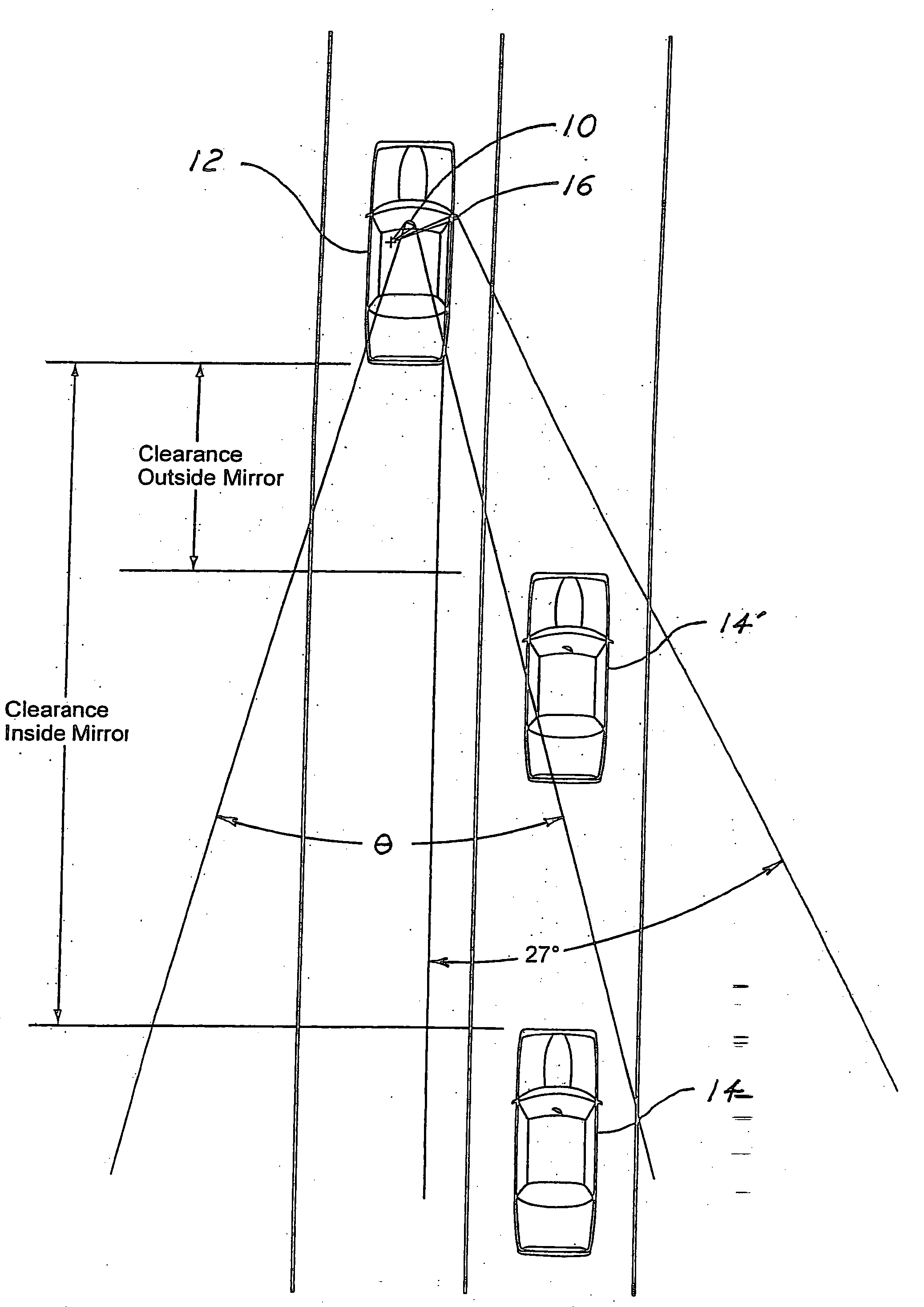
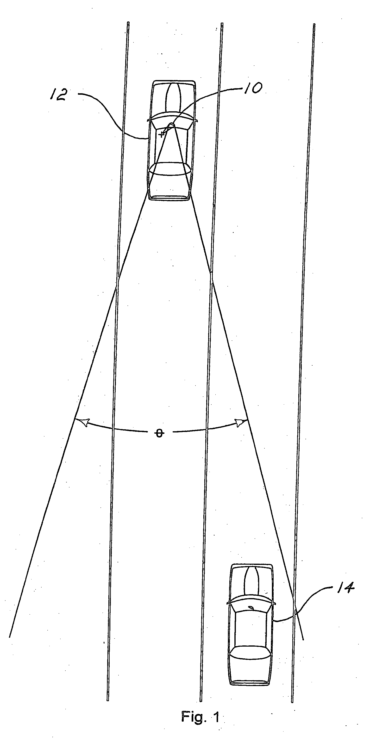
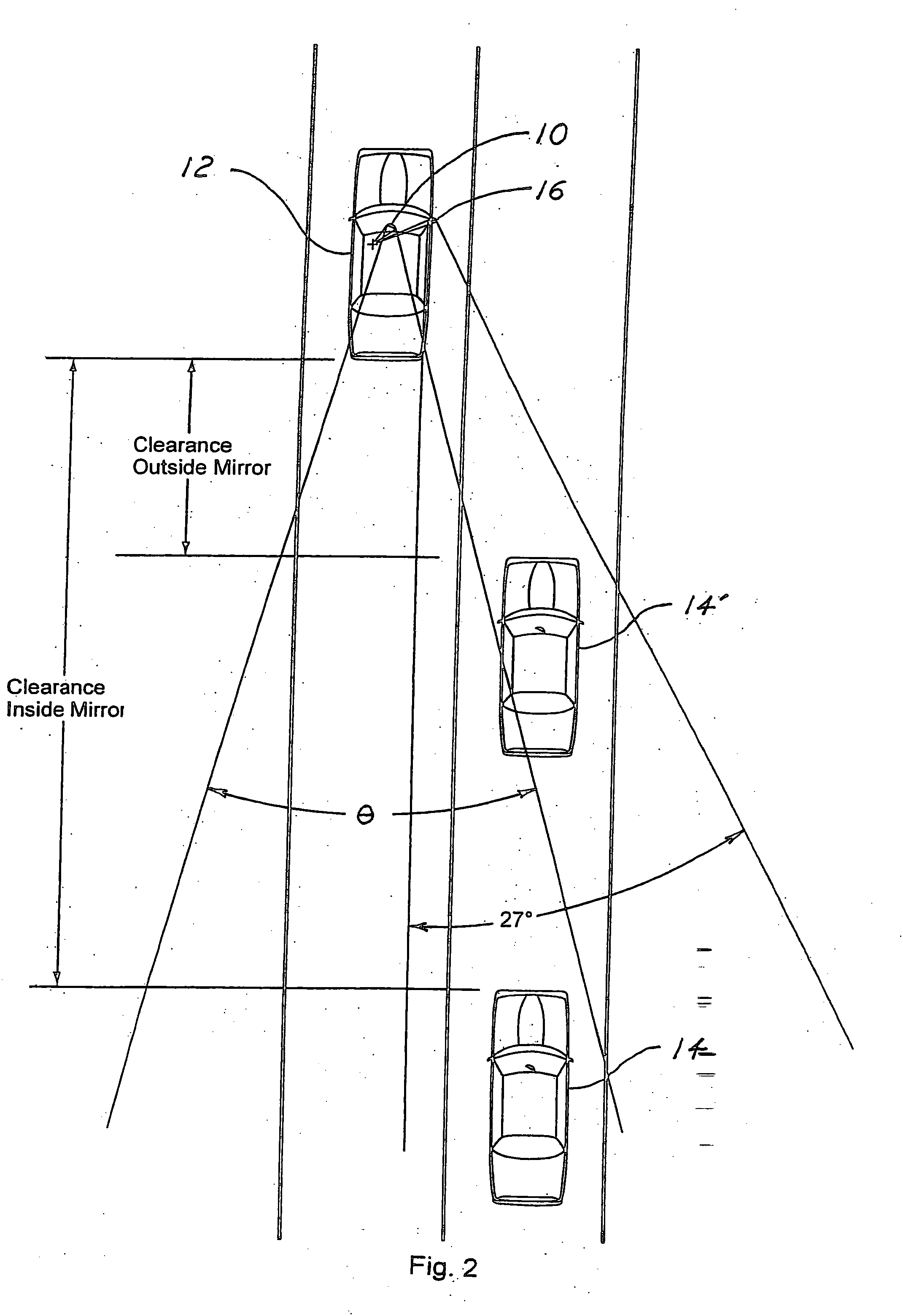
[0021]FIG. 1 shows the field of view, θ, of an inside rearview mirror 10 on a leading passenger car 12 and a trailing passenger car 14 whose front end is entirely visible in mirror 10. Most passenger cars today have a wide enough rear window and a wide enough inside rearview mirror to provide a total viewing angle of about 30° or 15° right and left. This characteristic of the inside rearview mirror has led to a widely used and very safe procedure for determining when it is safe to change lanes to the adjacent lane after having passed a vehicle in that lane. The National Safety Council (NSC) instructs its students in their Defensive Driving Training Course as follows: [0022]“It is safe to return to your lane only when you see the entire front of the vehicle you are passing in your inside rearview mirror. Before you actually move into the lane, check your right blind spot. Move smoothly into the right lane when it is safe.”

[0023] This is the procedure still taught today. Use of the c...


PUM


Abstract

An automotive system for determining when safe lane changes may be made is provided. The system includes an automotive outside rearview mirror for mounting on a vehicle including a main viewing section and a blindzone viewing section. The main viewing section has a viewing angle such that when the entire front end of a following vehicle in an adjacent lane is visible near the outer edge of the main viewing section, the following vehicle is at a clearance distance behind the vehicle. The blindzone viewing section has a viewing angle approximately encompassing the region between the outer limit of the viewing angle of the main viewing section and the peripheral vision line of a driver looking at the outside rearview mirror. The clearance distance is judged to be a safe separation distance for changing into the adjacent lane in front of the following vehicle.

Description

CROSS-REFERENCE TO RELATED APPLICATIONS [0001] This application claims the benefit of U.S. provisional application Ser. No. 60 / 566,053, filed Apr. 28, 2004.BACKGROUND OF THE INVENTION [0002] 1. Field of the Invention [0003] The present invention relates generally to automotive mirrors for determining safe lane change conditions. [0004] 2. Background Art [0005] Most passenger cars today are equipped with a convex mirror on the passenger's side of the vehicle. This is done because a planar, or unit magnification mirror, of a reasonable size on the passenger's side would have a narrow and relatively useless field of view. A planar mirror on the passenger's side having the same size as the mirrors currently used on the driver's side would have a viewing angle of about half that of the driver's side mirror. This results from the fact that the passenger's side mirror is about twice the distance away from the driver's eyes as compared to the driver's side mirror. This reduction in viewing ...

Claims


Application Information

Patent Timeline
IPC IPC(8): B60R1/08G02B5/08
CPCB60R1/081
Inventor PLATZER, GEORGE E. JR.
Owner PLATZER GEORGE E JR
Learn More