Can lid closure and method of joining a can lid closure to a can body

a technology of can lid closure and can body, which is applied in the field of containers, can solve the problems of inability to withstand internal pressure, difficulty in manufacturing, and failure to lower pressure,

Active Publication Date: 2005-11-17
METAL CONTAINERS
View PDF19 Cites 44 Cited by
  • Summary
  • Abstract
  • Description
  • Claims
  • Application Information

AI Technical Summary

Benefits of technology

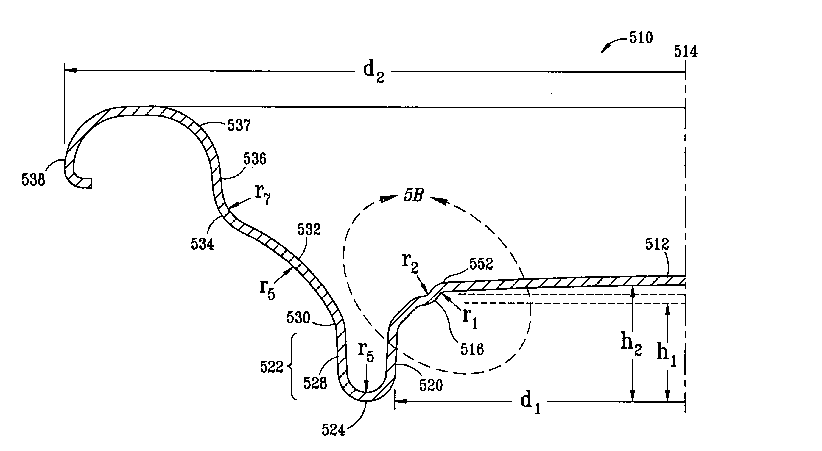
[0022] The present invention provides a lid for a can body. Specifically, the lid comprises a center panel having a central axis that is perpendicular to a diameter of an outer rim of the lid, where the center panel has a height that varies as a function of radial distance relative from the central axis. Extending radially outward from the center panel is a first step portion having negative concavity and having a radius of curvature less than about 0.015 inches. A second step portion, then, extends radially outward from the first step portion having a positive concavity and having a radius of curvature less than about 0.015 inches. From there, an angled inner wall extends radially outward from the second step portion having an angle from a line extending through each end of the angled inner wall relative to the central axis of less than about 50°. Additionally, an annular countersink portion extends radially outward from the center panel, and a chuckwall extends from the annular countersink. Finally, a peripheral curl portion extends radially outward from the chuckwall.

Problems solved by technology

It has been found that the can lid of U.S. Pat. No. 6,065,634 is susceptible to increased metal deformation during seaming and resulting failure at lower pressures.
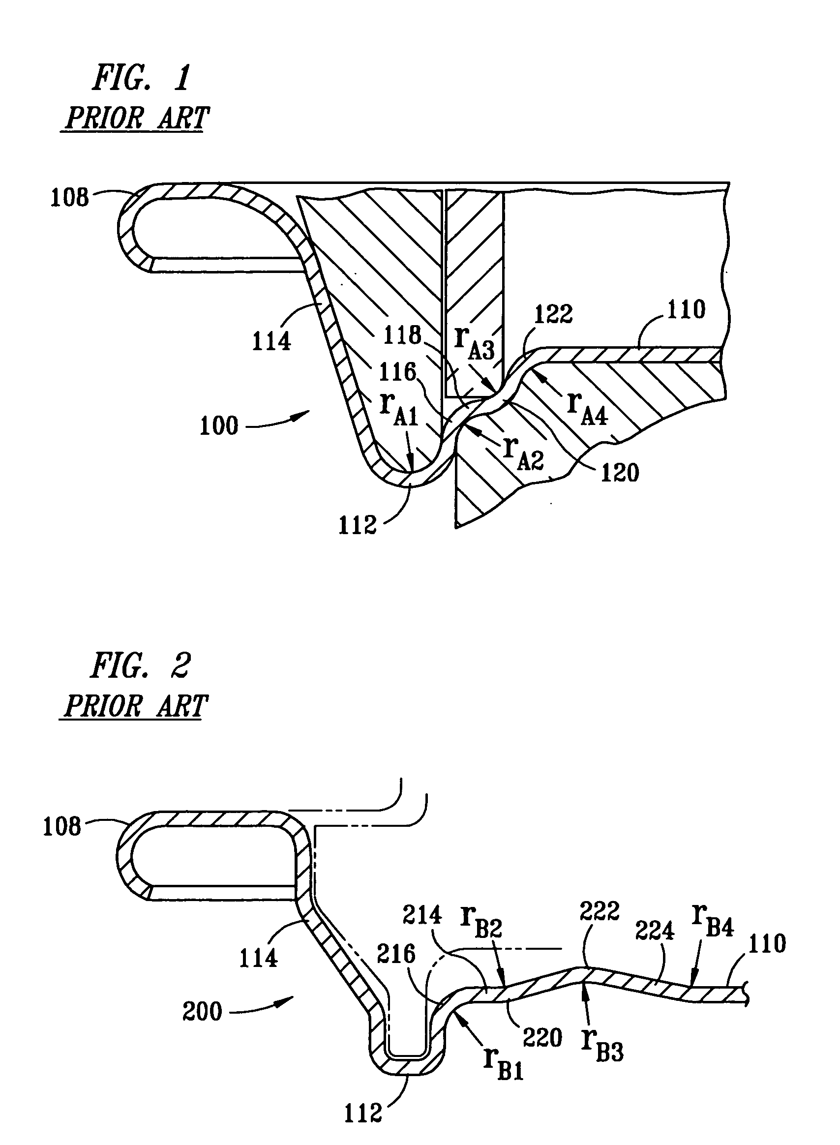
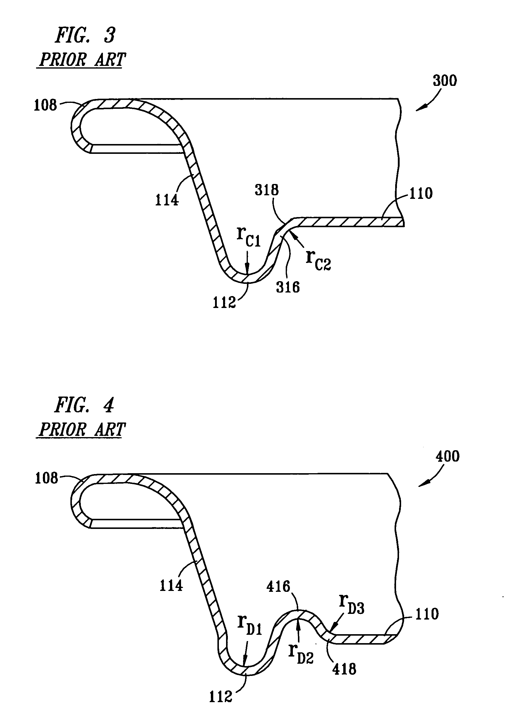
Each of these varying designs poses a particular subset of problems, such as difficulty in manufacturing, inability to withstand internal pressures, cost, and so forth.

Method used


Image

  • Can lid closure and method of joining a can lid closure to a can body
  • Can lid closure and method of joining a can lid closure to a can body
  • Can lid closure and method of joining a can lid closure to a can body

Examples


Embodiment Construction

[0044] The present invention is described in the following text by reference to drawings of examples of how the invention can be made and used. The drawings are for illustrative purposes only and are not necessarily exact scale representations of the embodiments of the present invention. In these drawings, the same reference characters are used throughout the views to indicate like or corresponding parts. The embodiments shown and described herein are exemplary. Many details are well known in the art, and as such are neither shown nor described. It is not claimed that all of the details, parts, elements, or steps described and shown were invented herein. Even though numerous characteristics and advantages of the present invention have been described in the drawings and accompanying text, the description is illustrative only, and changes may be made, especially in matters of arrangement, shape and size of the parts, within the principles of the invention to the full extent indicated ...


PUM


Abstract

Over the years there have been numerous attempts to improve the can lid oftentimes found on aluminum beverage can lids. The aims have traditionally been to reduce costs and improve performance. These aims have been accomplished through a variety of means, such as creating different formations within the can lid to reduce the amount of metal used while maintaining performance levels. Here, step portions are utilized between the annular countersink and the center panel of the can lid that cause a curvature of the center panel or to simply provide an angled inside wall. These formations, thus, reduce the amount of metal used while maintaining quality and yielding the desired performace.

Description

CROSS-REFERENCE TO RELATED APPLICATION [0001] This application is a continuation-in-part of U.S. patent application Ser. No. 10 / 752,928 entitled “CAN LID CLOSURE AND METHOD OF JOINING A CAN LID CLOSURE TO A CAN BODY,” filed on Jan. 7, 2004 which is a continuation of U.S. patent application Ser. No. 10 / 153,364, now U.S. Pat. No. 6,702,142, entitled “CAN LID CLOSURE AND METHOD OF JOINING A CAN LID CLOSURE TO A CAN BODY,” filed on May 22, 2002 which was a continuation of U.S. patent application Ser. No. 09 / 456,345, now U.S. Pat. No. 6,499,622, entitled “CAN LID CLOSURE AND METHOD OF JOINING A CAN LID CLOSURE TO A CAN BODY,” filed on Dec. 8, 1999 for inventor / applicant Christopher G. Neiner, wherein each related application is incorporated by reference herein for all purposes.TECHNICAL FIELD [0002] The present invention relates generally to containers, particularly to metallic beverage cans, and more particularly to metallic beverage can end closures adapted for interconnection to metal...

Claims


Application Information

Patent Timeline
Patent Type & Authority Applications(United States)
IPC IPC(8): B65D6/28B65D8/04
CPCB65D17/08
Inventor REED, JAMESNEINER, CHRISTOPHER G.
Owner METAL CONTAINERS
Why Eureka
Try Eureka