
Autostereoscopic electronic camera

a technology of electronic cameras and autostereoscopic images, applied in the field of three-dimensional imaging, can solve the problems of high satisfaction, expensive and labor-intensive undertaking, and achieve the effect of high satisfactory results

Inactive Publication Date: 2005-11-17
MCKEE WILLIAM JAMES
View PDF5 Cites 16 Cited by
  • Summary
  • Abstract
  • Description
  • Claims
  • Application Information

AI Technical Summary

Problems solved by technology

One of the main drawbacks in the successful proliferation of three dimensional imaging has always been the creation of satisfactory content to display.
None have proven to be highly satisfactory while the process remains an expensive and labor intensive undertaking.

Method used


Image

  • Autostereoscopic electronic camera
  • Autostereoscopic electronic camera
  • Autostereoscopic electronic camera

Examples


Embodiment Construction

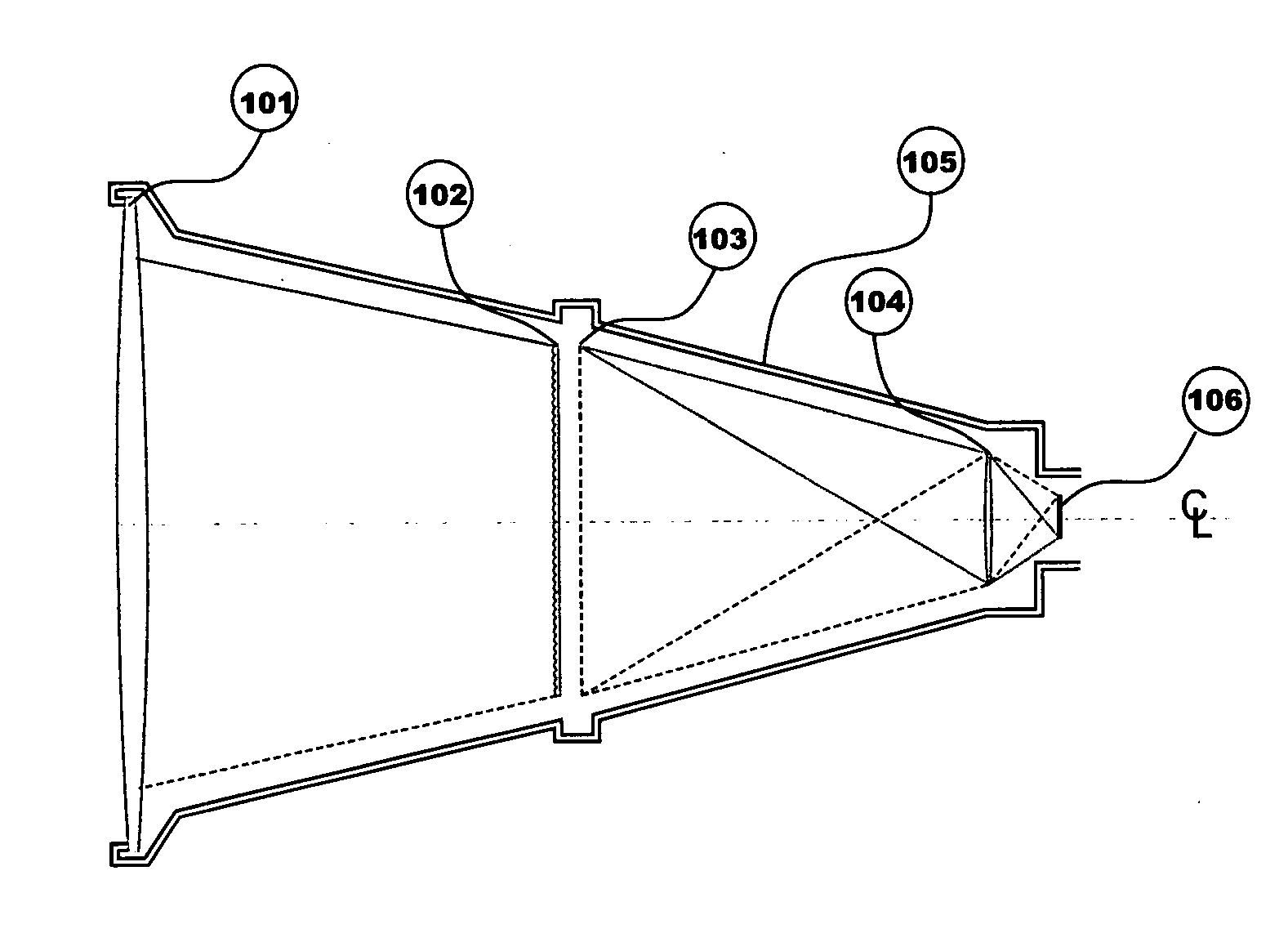
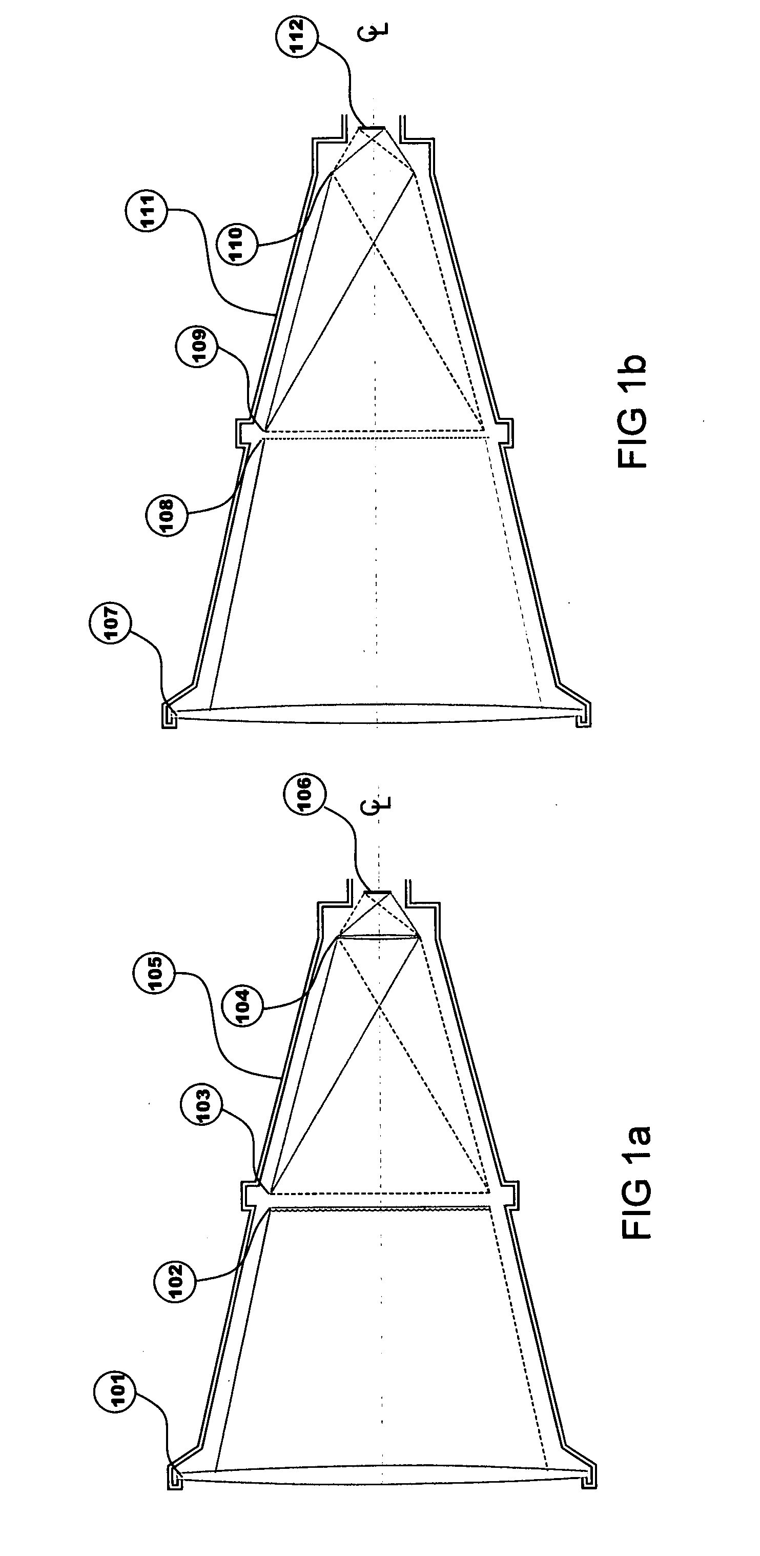
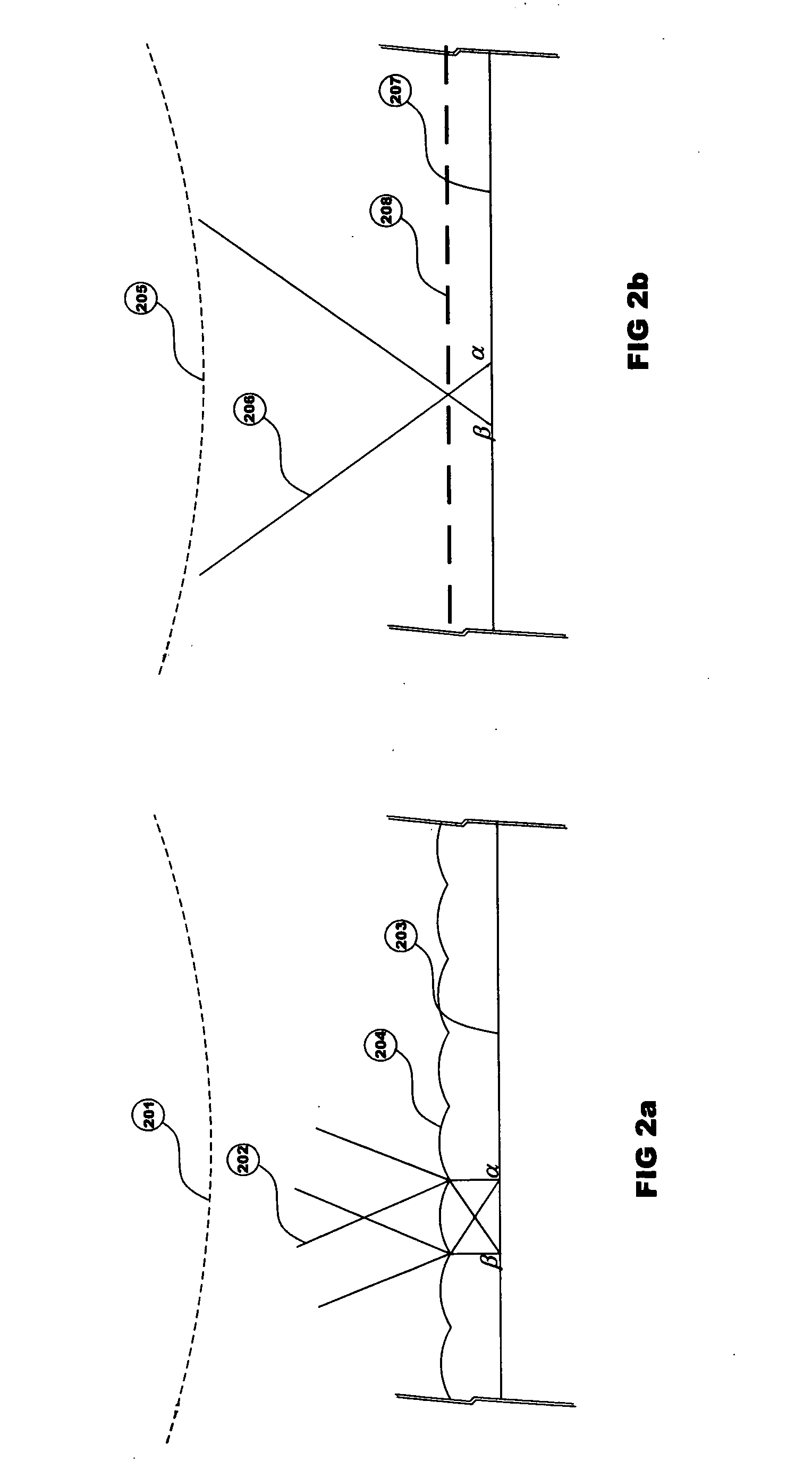
[0022] The invention is a camera based on electronic imaging technology that has been configured with an optical system that encodes the scene information into a complex proprietary image format that may be output in a “standard” timing format common in the industry. The camera may have any of a variety of output format signals such as R-G-B, NTSC, PAL, CCIR, 1080p, 720i, DVI, Y / C, Sony Component, “S-Video”, RS-170, RS-330, as well as other international, European or Asian format.

[0023] The camera may be of the closed circuit video camera, digital snapshot camera, professional level studio video camera, or other similar camera types employing a single image sensor or a group of sensors such as the three Red-Green-Blue channels acting together as one. For simplicity of explanation, the remainder of the text will use the singular sensor as the example with the understanding that this does not exclude the R-G-B trio of sensors that act as a single sensor in the imaging pickup of typic...


PUM


Abstract

The Electronic Autostereoscopic Camera comprises a taking “lens” that gathers full scene information and encodes this information onto the camera electronic sensor such that the “Depth” of the scene constituents is thereby preserved. This camera may be of a monochrome, single sensor color, or multi-sensor color type and may utilize C.C.D., Analog, C.M.O.S., or other variety of photosensitive electronic sensor. The output information from the camera may be in any suitable format suitable for use in the C.C.T.V., Broadcast T.V., or A / V displays (Computer Generated). Post processing and recording of the data is handled in the same manner as the familiar Two-Dimensional content now utilized by such industries and users. The “lens” of this camera may be configured to function on other electronic cameras by fitting the scene “Depth Encoding” optical group to a particular camera as may be desired by the user. These cameras may include Simple Hand Held, Shoulder Mounted, Tripod Mounted, Laboratory, Studio, or Vehicle Mounted models of various design and manufacture.

Description

CROSS REFERENCE TO RELATED APPLICATIONS [0001] This application refers to the preliminary patent application posted on May 10, 2003 entitled “AUTOSTEREOSCOPIC ELECTRONIC CAMERA, and refers to the disclosure document filed on May 31, 2002 entitled “ELECTRONIC THREE DIMENSIONAL PANORAMIC IMAGING SYSTEM”, holding the document disclosure No. 512247 from the USPTO disclosure document program. FEDERALLY SPONSORED RESEARCH OR DEVELOPMENT [0002] Not Applicable REFERENCE TO A MICROFICHE APPENDIX [0003] Not Applicable BACKGROUND OF THE INVENTION [0004] The field of three dimensional imaging has a long road of research and development throughout several centuries. Since we, as humans, exist in a three dimensional world it is a natural desire to view displays in depth just as if we were viewing it directly. Within the past two decades a number of different scientific, academic, and commercial entities have been pursuing the field of “Autostereoscopic” displays; one that precludes the need for a...

Claims


Application Information

Patent Timeline
IPC IPC(8): G03B7/099G03B35/08G03B35/24H04N13/229H04N13/305
CPCG03B35/08G03B35/24H04N13/0225H04N13/0409H04N13/0232H04N13/0404H04N13/0406H04N13/0228H04N13/305H04N13/232H04N13/229H04N13/31H04N13/225H04N13/307
Inventor MCKEE, WILLIAM JAMES
Owner MCKEE WILLIAM JAMES
Learn More