Variable speed drive for agricultural seeding machines

a variable speed drive and seeding machine technology, applied in the field of agricultural seeding machines, can solve the problems of consuming an excessive amount of electric power, unable to control individual row units, and unable to affect so as to achieve the effect of small and compact, not affecting the overall size of the row uni

Active Publication Date: 2005-11-24
DEERE & CO
View PDF26 Cites 18 Cited by
  • Summary
  • Abstract
  • Description
  • Claims
  • Application Information

AI Technical Summary

Benefits of technology

[0009] An advantage of the present invention is that the primary input power to the seed meter is derived from the mechanical ground drive and the rotational speed of the input power is controlled using a smaller electric motor.
[0010] Another advantage is that the planetary gear set may be relatively small and compact, thus not affecting the overall size of the row unit.
[0011] Yet another advantage is that the electric motor which controls the rotational speed of the output shaft from the planetary gear set may be controlled using a feedback loop dependent upon the operating speed of the seed meter.

Problems solved by technology

The mechanisms necessary to properly meter the seeds, dispense the seeds at a predetermined rate and place the seeds at predetermined relative locations within a seed trench are relatively complicated.
Such systems may be relatively expensive, complicated and lack control on an individual row unit basis.
Driving each seed meter with a corresponding electric motor requires a relatively large electric motor which consumes an excessive amount of electric power which is not typically available for current traction units (e.g., tractor) used for pulling the seeding machine.
Using an all-electrical drive of this type therefore is not practical with existing traction units.

Method used


Image

  • Variable speed drive for agricultural seeding machines
  • Variable speed drive for agricultural seeding machines
  • Variable speed drive for agricultural seeding machines

Examples


Embodiment Construction

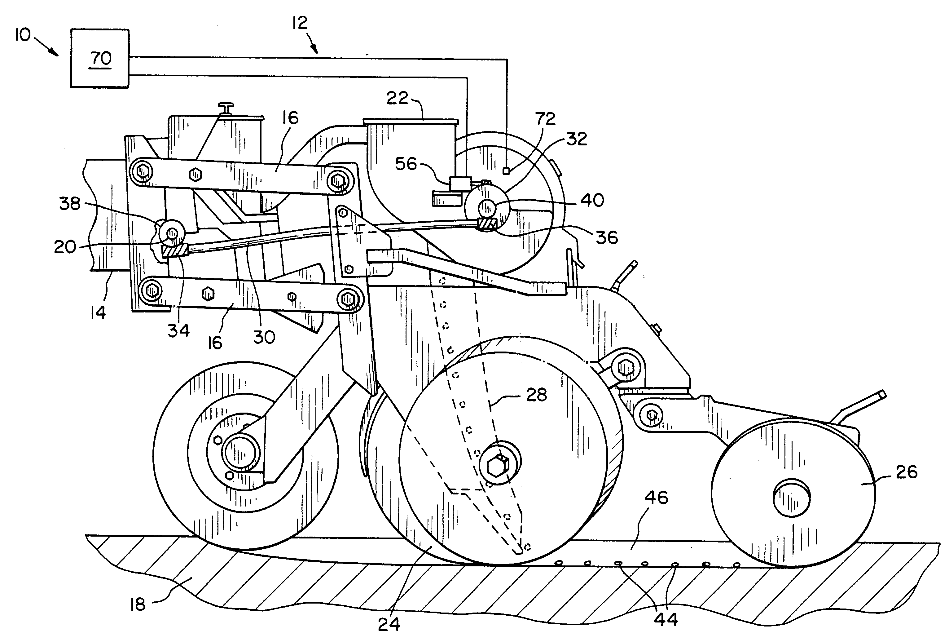
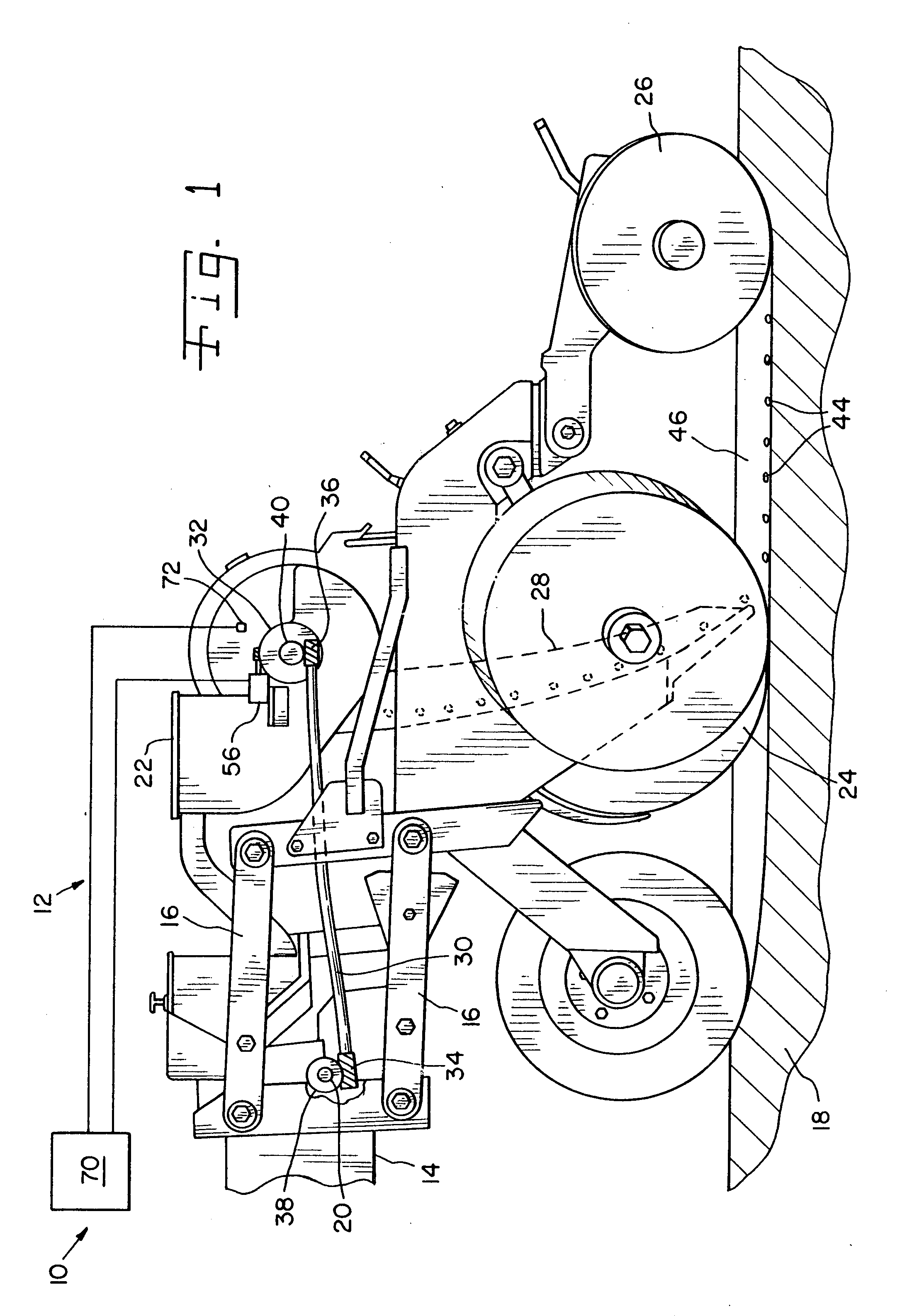
[0016] Referring now to the drawings, and more particularly to FIGS. 1 and 2, there is shown an embodiment of an agricultural seeding machine 10 of the present invention. In the embodiment shown, seeding machine 10 includes a plurality of individual row units 12 coupled with a tool bar or frame 14. Each row unit 12 is typically configured substantially identical to each other, and therefore only a single row unit 12 is shown and described in the drawings.

[0017] Row unit 12 is coupled with frame 14 through pivotal linkage elements 16, and thereby is moveable in generally vertical up and down directions to follow the contour of soil 18. A ground driven main shaft 20 runs along the backside of frame 14 and is the primary source of input power to each seed meter 22.

[0018] Each row unit 12 also includes other components such as trench openers 24, trench closers 26, a drop tube 28, etc. which may be of conventional design and therefore not described in further detail herein.

[0019] The ...


PUM


Abstract

An agricultural seeding machine includes a mechanical drive; a seed meter including a driven shaft; and a planetary gear set. The planetary gear set includes an input shaft connected with the drive, an output shaft connected with the driven shaft, a ring gear, and a motor coupled with a ring gear.

Description

FIELD OF THE INVENTION [0001] The present invention relates to agricultural seeding machines, and, more particularly, to an input drive for a seed meter in such an agricultural seeding machine. BACKGROUND OF THE INVENTION [0002] An agricultural seeding machine such as a row crop planter or grain drill places the seeds at a desired depth within a plurality of parallel seed trenches formed in the soil. In the case of a row crop planter, a plurality of row crop units are typically ground driven using wheels, shafts, sprockets, transfer cases, chains and the like. Each row crop unit has a frame which is movably coupled with a tool bar. The frame may carry a seed hopper, herbicide hopper and / or insecticide hopper. The mechanisms necessary to properly meter the seeds, dispense the seeds at a predetermined rate and place the seeds at predetermined relative locations within a seed trench are relatively complicated. [0003] The mechanisms associated with metering and placing the seeds general...

Claims


Application Information

Patent Timeline
Patent Type & Authority Applications(United States)
IPC IPC(8): A01C7/00A01C9/00A01C19/02
CPCA01C19/02A01C19/04
Inventor LANDPHAIR, DONALD KEITHMYERS, CHRISTOPHER ALLEN
Owner DEERE & CO
Why Eureka
Try Eureka