Collapsible keyboard

a keyboard and collapsible technology, applied in the field of collapsible keyboards, can solve the problems of difficult positioning of the bracket, etc., and achieve the effect of convenient carrying and storage and thin profil

Inactive Publication Date: 2005-11-24
DARFON ELECTRONICS CORP
View PDF3 Cites 12 Cited by
  • Summary
  • Abstract
  • Description
  • Claims
  • Application Information

AI Technical Summary

Benefits of technology

[0005] The invention provides a collapsible keyboard wi...

Problems solved by technology

It is difficult, however, to position the br...

Method used


Image

  • Collapsible keyboard
  • Collapsible keyboard
  • Collapsible keyboard

Examples


Embodiment Construction

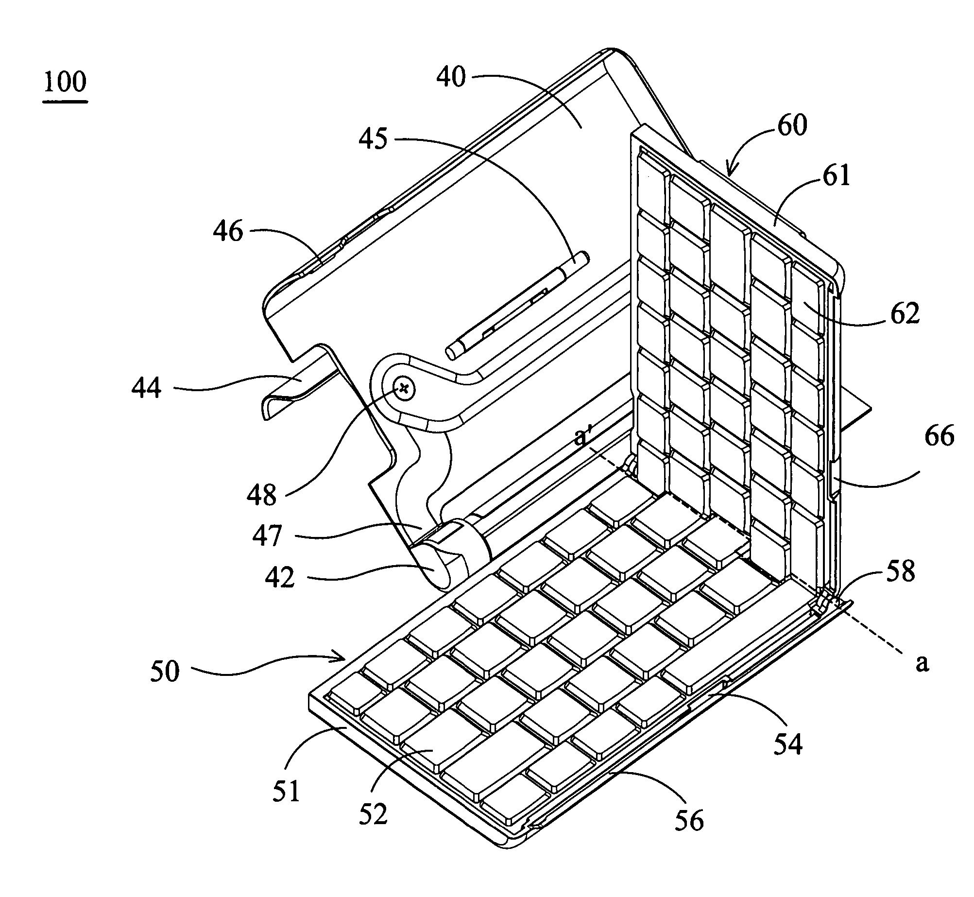
[0021] In FIG. 3A, a collapsible keyboard 100 of the invention is situated in an operating mode, i.e., the same mode of a conventional keyboard. The collapsible keyboard 100 comprises a connection part 30, a top cover 40 pivoted to the connection part 30, a first key assembly 50 connected to the connection part 30 and movable between a first position and a second position, a shaft 42, a supporting plate 44, a shaft 45, a shaft 58, and a second key assembly 60 pivoted to the right side of the first key assembly 50 by the shaft 58.

[0022] When the collapsible keyboard 100 is in an operating mode, the first key assembly 50 is located at the first position and the second key assembly 60 is located between the first key assembly 50 and the top cover 40, and the first and second key assemblies 50 and 60 are substantially located on the same level. When the collapsible keyboard 100 is in a collapsed mode, the second key assembly 60 is disposed on the first key assembly 50 and the top cover...


PUM


Abstract

A collapsible keyboard comprises a connection part, a top cover pivoted to the connection part, a first key assembly connected to the connection part and movable between a first position and a second position, and a second key assembly pivoted to the first key assembly. The first key assembly is located at the first position when the collapsible keyboard is in an operating mode, and the second key assembly is located between the first key assembly and the top cover and the first key assembly is located at the second position when the collapsible keyboard is in a collapsed mode.

Description

BACKGROUND [0001] The invention relates to a keyboard, and in particular to a collapsible keyboard. [0002]FIG. 1 is a schematic view of a conventional bi-fold keyboard 10. The keyboard 10 comprises a left key part 12, a right key part 14, a shaft 16 and a bracket 18 connected to the left key part 12. The left key part 12 is pivoted to the right key part 14 via the shaft 16. When the left key part 12 and the right key part 14 are folded together via the shaft 16 into a received mode, the size of the folded keyboard 10 is only reduced by half. [0003] The bracket 18 connected to the left key part 12 (or the right key part 14) serves as a support for a portable electronic device, e.g. personal digital assistant (PDA). Typically, the electronic device supported by the bracket 18 must be moved to a central region 18′ of the keyboard 10 to be viewable. It is difficult, however, to position the bracket 18 at the center of the unfolded keyboard 10. [0004]FIG. 2 is another schematic view of a...

Claims


Application Information

Patent Timeline
IPC IPC(8): G06F3/02H01H9/00
CPCG06F3/0221H01H2223/05H01H13/86
Inventor LIU, CHIA-HUNGCHIN, KUO-CHIANG
Owner DARFON ELECTRONICS CORP
Why Eureka
Try Eureka