Power converter system having adaptor unit for generating multiple output voltage values

a power converter and adaptor unit technology, applied in the direction of power conversion systems, power supply for data processing, coupling device connections, etc., can solve the problems of more limited heat dissipation space inside the key, damage, and damage of electronic devices,

Active Publication Date: 2005-11-24
DELTA ELECTRONICS INC
View PDF6 Cites 18 Cited by
  • Summary
  • Abstract
  • Description
  • Claims
  • Application Information

AI Technical Summary

Benefits of technology

[0035] Preferably, the buck converter circuit further includes a power converter subsystem, and the power converter subsystem is employed with a second set of plurality of adaptor units to convert the relatively higher DC output voltage into the relatively lower DC output voltage having a plurality of different voltage values.
[0036] Preferably, the power converter system and the power converter subsystem have different sets of design parameters including the number of the adaptor units, the output voltage with various voltage values, the relatively lower DC output voltage with different voltage values, number of resistors, and resistance values, and the main body component of the power converter system and a main body component of the power converter subsystem can be both installed in the case.
[0037] Preferably, the power converter circuit further includes a converter shut-down circuit, the converter shut-down circuit is employed when the power converter circuit is in one of an over-current status and an over-voltage status, and the power converter circuit has an over-current protection circuit and an over-voltage protection circuit for receiving an over-current / over-voltage control signal and outputting a shut-down control signal respectively so as to shut-down the power converter circuit.

Problems solved by technology

Thus, how to convert the voltages offered by the different external power sources (AC or DC) into the certain form and within the proper range so as to be properly employed by the electronic device (including electronic equipment) is an important issue.
But, when the above-mentioned switching device is employed, it is quite possible that the electronic device (including electronic equipment), which uses the output voltage generated by the power converter through changing the position of the switching device, is damaged due to that the user chooses an incorrect output voltage by mistake especially when the incorrect output voltage is higher than the voltage required by the electronic device (including electronic equipment).
As for the key having an electronic element inside, the heat-dissipating space inside the key is more limited than that of the power converter.
While the key is employed for a relatively longer time period, either the key is damaged or the life-span of the key is shortened due to that the heat is generated inside the key by the electronic element and the heat-dissipating condition inside the key is relatively poor.
When the key is broken (short-circuited or open-circuited), the output voltage value of the power converter is abnormal, and the electronic device (including electronic equipment), which employs the output voltage of the power converter, would be damaged.
When the output voltage value is abnormal, the electronic device (including electronic equipment), which employs the output voltage, would be damaged.

Method used


Image

  • Power converter system having adaptor unit for generating multiple output voltage values
  • Power converter system having adaptor unit for generating multiple output voltage values
  • Power converter system having adaptor unit for generating multiple output voltage values

Examples


Embodiment Construction

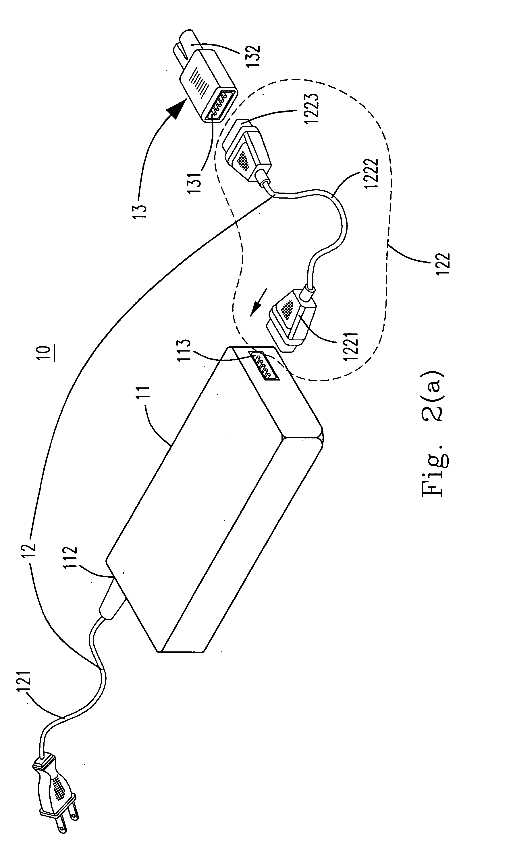
[0055] Due to the drawbacks of the converters employing the switching devices to change the output voltages and the converters employing the plurality of keys each having an electronic element inside to determine the output voltages respectively in the prior art, the first preferred embodiment of the proposed power converter system 10 of the present invention as shown in FIGS. 2(a) to 2(c) are provided. The proposed power converter system 10 is a single input converter, which means it could only receive either a DC power source or an AC power source. Please refer to FIGS. 2(a) to 2(c), the proposed power converter system 10 of the present invention includes a main body component 11, an input terminal 112, a first connecting port 113, a power cord 12 including an input power cord 121 and an output power cord 122 (having a second connecting port 1221, a connecting cord 1222, and a third connecting port 1223) and an adaptor unit including an adaptor 13 (the adaptor unit could include t...


PUM


Abstract

The proposed power converter system includes: a main body component having a case, an input terminal, a power converter circuit electrically connected to the input terminal, a plurality of resistors electrically connected to the power converter circuit, and a first connecting port electrically connected to each of the resistors, and a plurality of adaptor units each having an adaptor. Each of the adaptors is employed to let the power converter circuit generate a specific output voltage value and includes: an input connecting port coupled to the first connecting port to let each of the resistors become one of the grounded state, the open-circuited state, and the coupled to the output voltage state, and an output port coupled to the input connecting port for outputting the output voltage.

Description

FIELD OF THE INVENTION [0001] The present invention relates to a power converter system. More specifically, this invention relates to a power converter system having a plurality of adaptor units for generating multiple output voltage values. BACKGROUND OF THE INVENTION [0002] Generally speaking, any electronic device (including electronic equipment) must be powered by an external power source except for employing the electronic cells. Thus, how to convert the voltages offered by the different external power sources (AC or DC) into the certain form and within the proper range so as to be properly employed by the electronic device (including electronic equipment) is an important issue. [0003] The power converter is just such a device for the above-mentioned requirements. Usually, the power converters can be further divided into the AC-DC converters, the DC-DC converters, etc. according to the voltage converting types of the converters. The users can make the proper choices of differen...

Claims


Application Information

Patent Timeline
Patent Type & Authority Applications(United States)
CPCG06F1/26H01R31/065H01R31/06H01R13/6675
Inventor CHIANG, CHIN-TSAI
Owner DELTA ELECTRONICS INC
Why Eureka
Try Eureka