Piggyback forklift truck and method of operating same

Active Publication Date: 2013-10-17
MOFFETT RES & DEV
View PDF8 Cites 1 Cited by
  • Summary
  • Abstract
  • Description
  • Claims
  • Application Information

AI Technical Summary

Benefits of technology

The invention is a piggyback forklift truck that has a rechargeable battery pack that can be recharged while moving from one location to another. This is achieved by connecting the forklift truck to a carrying vehicle while in transit, and using an electrical power take off feed from the carrying vehicle to charge the battery pack on the forklift truck. This allows the forklift truck to operate for longer periods of time between charges.

Problems solved by technology

Furthermore, the piggyback forklift trucks must be compact in a fore and aft sense as the amount by which the piggyback forklift truck may protrude from the rear of the carrying vehicle (commonly referred to as “overhang”) is restricted by law in many jurisdictions.
In addition to this, the greater the overhang, the greater the forces applied to the mounting kit and piggyback forklift equipment used to mount the piggyback forklift on the carrying vehicle.
Increased forces necessitate reinforcement of these components which typically leads to increased weight which as described above is highly undesirable.
Heretofore, electric motors have been deemed unsuitable for use with piggyback forklift trucks.
This large battery will be heavy and will increase the dimensions of the piggyback forklift truck and is therefore undesirable for use with a piggyback forklift truck.
Secondly, due to the fact that the piggyback forklift trucks are used far away from the operators premises and the battery charging equipment, if the piggyback forklift truck runs out of battery power when located remotely from the operator's premises, this would present a significant problem to the operator as they would have to send specialised equipment to retrieve the piggyback forklift truck.

Method used


Image

  • Piggyback forklift truck and method of operating same
  • Piggyback forklift truck and method of operating same
  • Piggyback forklift truck and method of operating same

Examples


Embodiment Construction

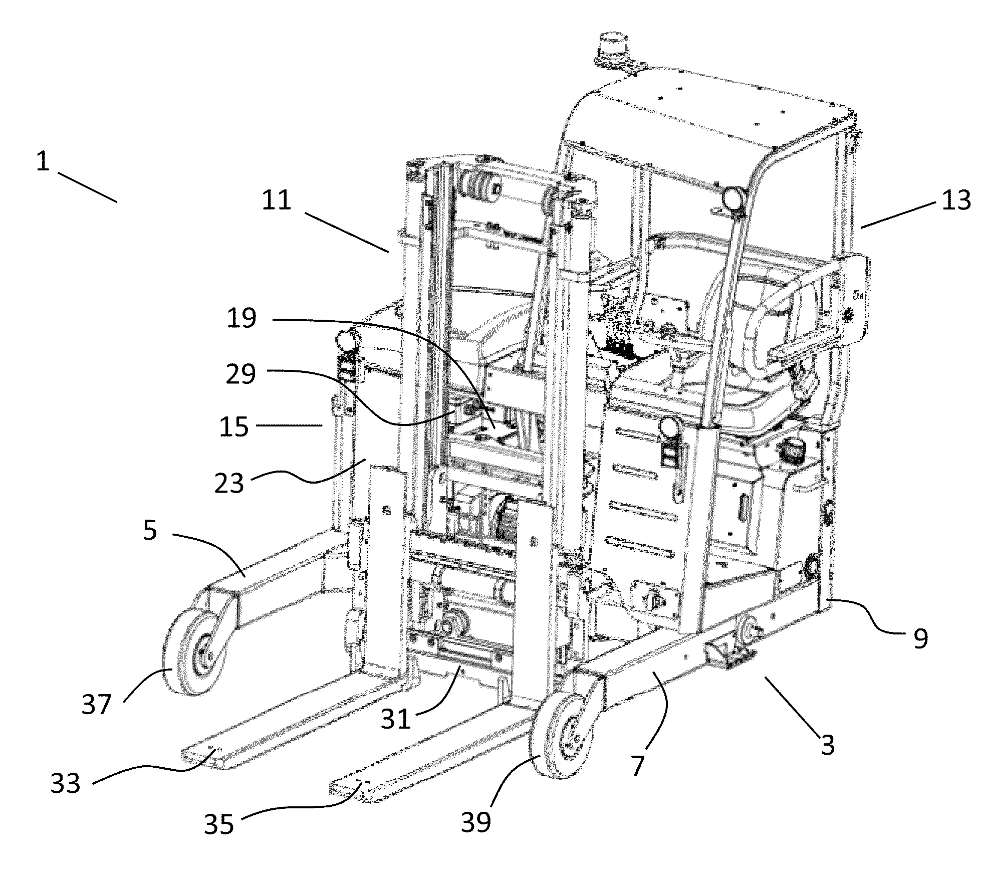
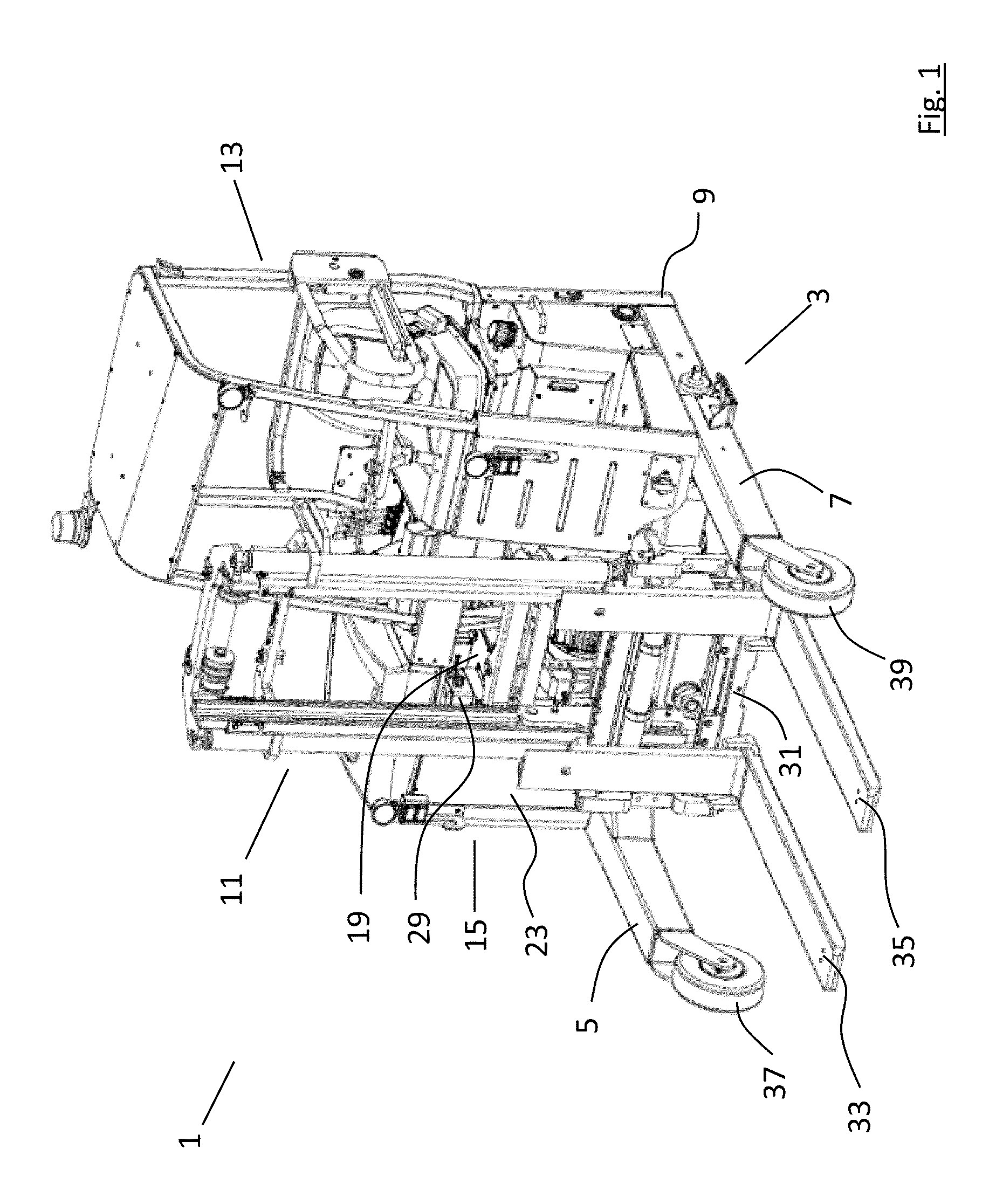
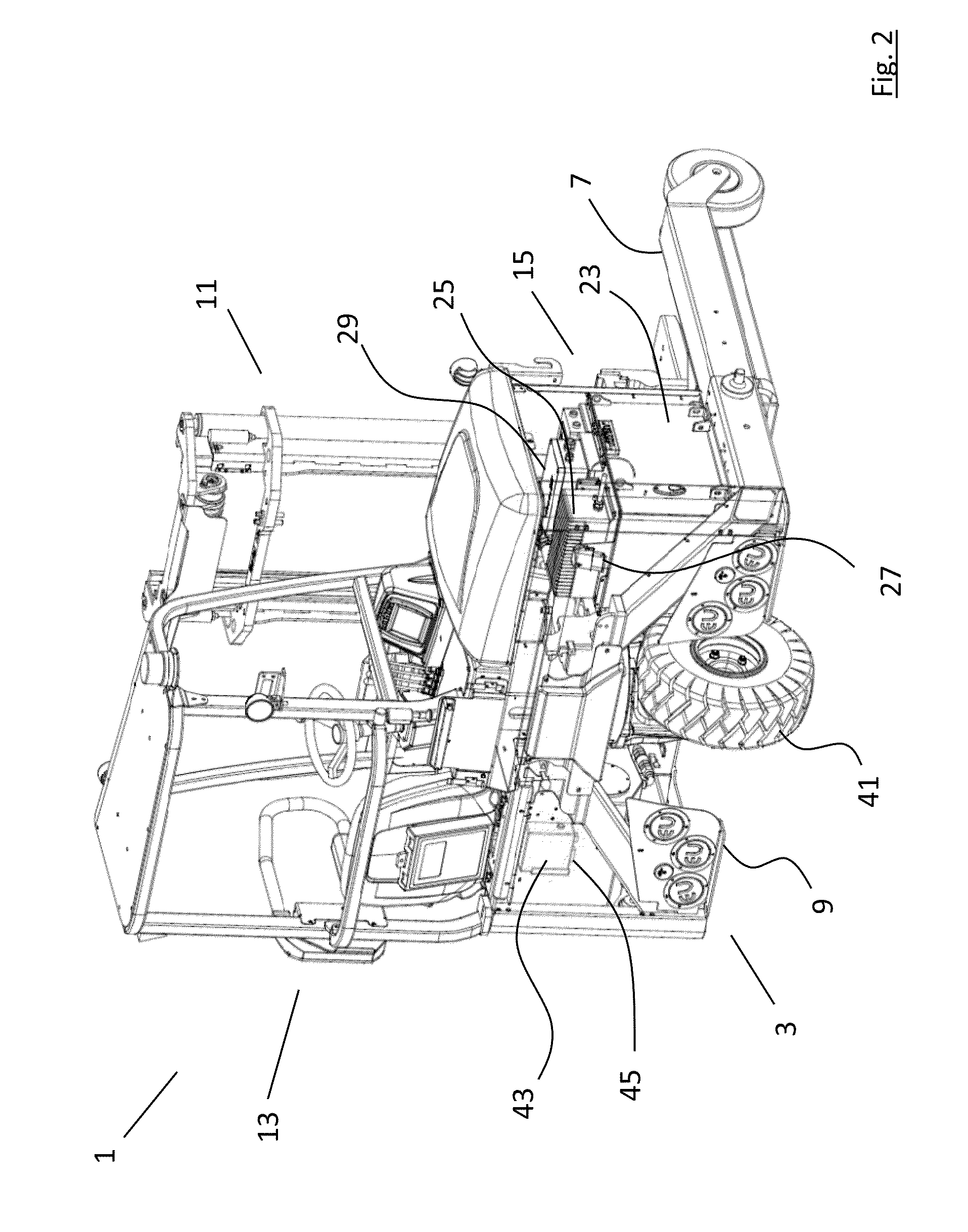
[0049]Referring to FIGS. 1 and 2, there is shown a piggyback forklift truck, indicated generally by the reference numeral 1, comprising a wheeled U-shaped chassis 3 comprising a pair of forwardly projecting side bars 5, 7 bridged by a transverse rear crossbar 9. The piggyback forklift truck 1 comprises a lifting assembly 11 mounted on the chassis 3 intermediate the pair of forwardly projecting side bars 5, 7, a driver's seating station 13 mounted on the chassis rearward of the lifting assembly, and a motive power unit 15 mounted on the chassis. The piggyback forklift truck is electrically powered and the motive power unit 15 comprises a primary electric drive motor, a secondary lifting assembly motor and a tertiary steering motor. The motive power unit 15 further comprises a rechargeable battery pack 23, in this case a Lithium Ion battery pack, for powering the electric motor, a battery pack charging unit 25 in electrical communication with the rechargeable battery pack 23 and a fir...


PUM


Abstract

This invention relates to a piggyback forklift truck and a method of operating same. The piggyback forklift truck comprises a motive power unit which includes an electric motor, a rechargeable battery pack powering the electric motor, a battery pack charging unit, a first electricity power supply connector in electrical communication with the battery pack charging unit, a DC / AC converter in electrical communication with the battery pack charging unit, and a second electricity power supply connector in electrical communication with the DC / AC converter, the second electricity power supply being arranged for reception of an electrical power take off feed from a carrying vehicle. In this way, the piggyback forklift truck can be charged by the mains supply when the carrying vehicle is not in transit and can be trickle charged while the carrying vehicle is in transit. This will maximize the operating time of the electrically powered piggyback forklift truck while it is making deliveries to customers.

Description

TECHNICAL FIELD OF THE INVENTION[0001]This invention relates to a piggyback forklift truck. More specifically, this invention relates to a piggyback forklift truck powered by an electric motor.BACKGROUND OF THE INVENTION[0002]Piggyback forklift trucks are a highly specialised type of lightweight forklift truck that can be mounted on the rear of an articulated chassis for transport to and from customer's premises. Once at the customer's premises, the piggyback forklift truck can be dismounted from the rear of the articulated chassis and used to load and unload goods from the articulated chassis before being remounted onto the rear of the articulated chassis for transport to the next customer's premises.[0003]Out of necessity, the piggyback forklift trucks must be lightweight as any increase in piggyback forklift truck weight will correspond to a decrease in available haulage capacity of the articulated chassis on which it is mounted. Furthermore, the piggyback forklift trucks must be...

Claims


Application Information

Patent Timeline
IPC IPC(8): B66F9/075B60L11/18
CPCB66F9/075B60L11/1811B60L2200/40B60L2200/42B60L2210/40B66F9/07563B66F9/205B60L53/14B60L53/20B60L53/22H02J7/14Y02T10/70Y02T10/7072Y02T10/72Y02T90/14Y02T90/16Y02T90/12
Inventor MCGRANE, BARRYTURNBULL, KEVIN
Owner MOFFETT RES & DEV
Why Eureka
Try Eureka