
Linear motor and manufacturing method thereof

a technology of linear motors and manufacturing methods, applied in the direction of electrical apparatus, mechanical energy handling, dynamo-electric machines, etc., can solve the problem of imposing a greater burden, and achieve the effect of minimizing the magnetic attraction force between the armature and the needl

Inactive Publication Date: 2005-12-01
HITACHI LTD
View PDF22 Cites 3 Cited by
  • Summary
  • Abstract
  • Description
  • Claims
  • Application Information

AI Technical Summary

Benefits of technology

This configuration reduces magnetic flux leakage, enhances magnetic flux efficiency, and minimizes the burden on support mechanisms by canceling attraction forces, resulting in improved thrust and reduced strain in the linear motor construction.

Problems solved by technology

According to the prior art, while a linear motor can be manufactured at a lower cost by means of a simplified construction and a simplified lead treatment, it involves the following problems.
In addition, since a magnetic attraction force acts between the armature 3 and the needle 6 in one way, a greater burden is imposed on the support mechanism of the needle 6, and, consequently, a strain is caused in the construction, resulting in various problems.

Method used


Image

  • Linear motor and manufacturing method thereof
  • Linear motor and manufacturing method thereof
  • Linear motor and manufacturing method thereof

Examples


Embodiment Construction

[0023] A preferred embodiment of the present invention will be described hereunder with reference to the drawings.

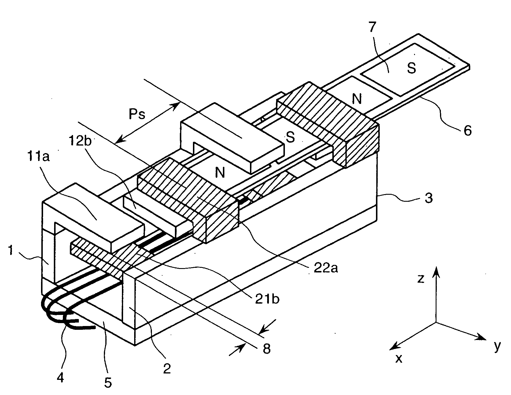
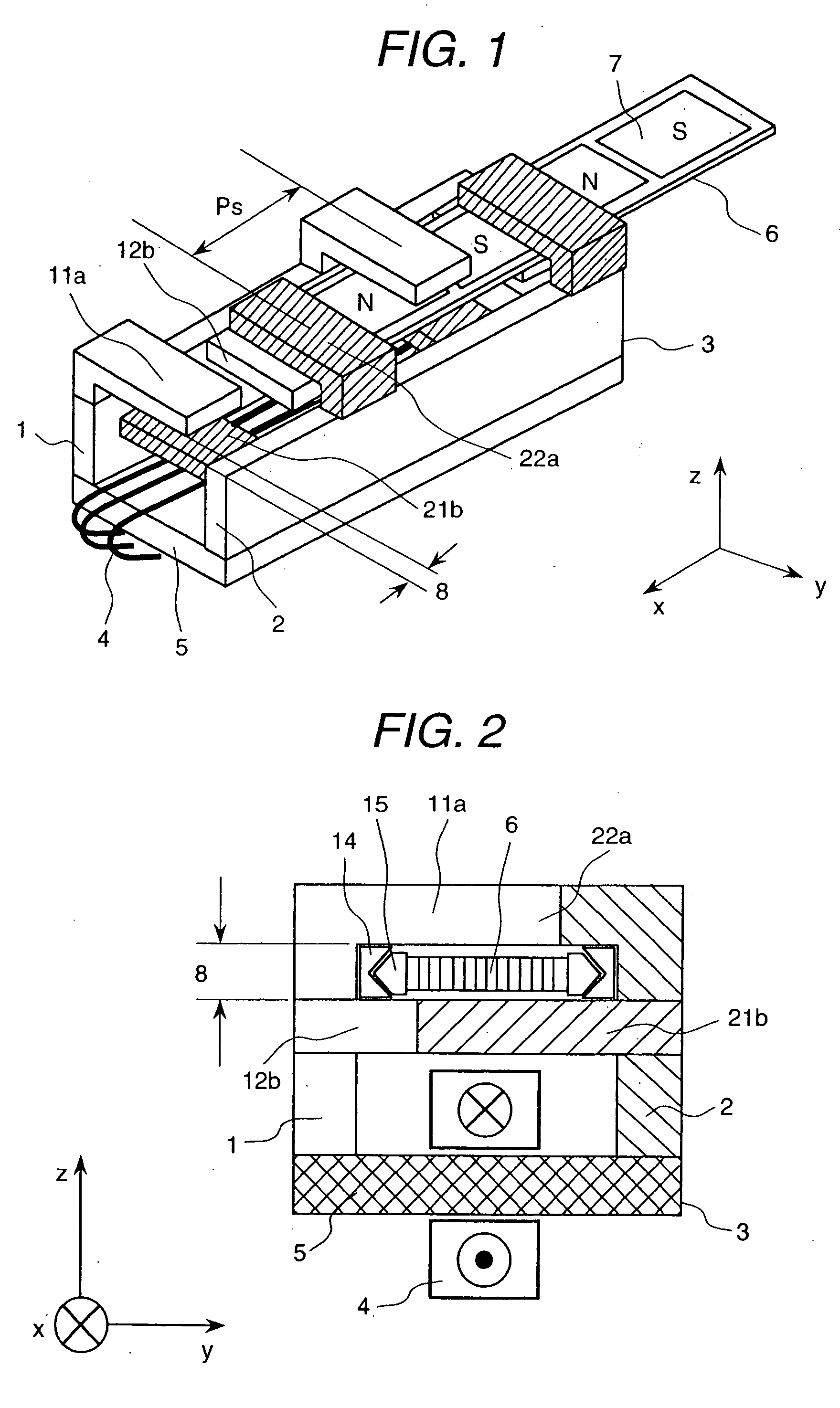
[0024]FIG. 1 is a diagram of a linear motor according to an embodiment of the present invention, and FIG. 2 shows a sectional view thereof.

[0025] In FIG. 1, the linear motor comprises a magnetic pole 1 having an upper magnetic pole tooth 11a and a lower magnetic pole tooth 12b, another magnetic pole 2 having a lower magnetic pole tooth 21b and an upper magnetic pole tooth 22a, an armature 3 having an armature coil 4 and an armature core 5, and a needle 6 having permanent magnets 7. A gap 8 is formed between the upper magnetic pole tooth 11a of the magnetic pole 1 and the lower magnetic pole tooth 21b of the magnetic pole 2 (as well as between the lower magnetic pole tooth 12b of the magnetic pole 1 and the upper magnetic pole tooth 22a of the magnetic pole 2). Ps denotes a center-to-center pole pitch between two adjacent magnetic pole teeth on the same upper or lower s...


PUM


Abstract

To reduce the magnetic flux leakage through the gap between magnetic pole teeth of an armature so as to reduce the magnetic attraction force generated between the armature and a needle, an armature unit is provided with two magnetic poles, on the top of which are magnetic pole teeth protruding toward the opposing magnetic pole, where the magnetic pole teeth of the magnetic pole are arranged at two heights, upper and lower, and the magnetic pole teeth of the opposing magnetic pole are arranged at two heights, upper and lower, so that the magnetic flux flows upward and downward alternately between the upper and lower magnetic pole teeth. The needle equipped with permanent magnets moves relatively in the gap between the upper and lower magnetic pole surfaces of the armature unit.

Description

CROSS-REFERENCE TO RELATED APPLICATIONS [0001] This is a continuation of application Ser. No. 10 / 810,614 filed 29 Mar. 2004, allowed, which is a continuation of application Ser. No. 09 / 959,615 filed 1 Nov. 2001 and issued as U.S. Pat. No. 6,825,581 B1, which is a U.S. National Stage of PCT / JP00 / 02808 filed 27 Apr. 2000, the entire contents of which are incorporated herein by reference in their entirety.BACKGROUND OF THE INVENTION [0002] The present invention relates to a linear motor to and a method of manufacture thereof; and more particularly, the invention relates to a linear motor that is provided with an armature on which a coil is to be wound and magnetic poles with pairs of opposing upper and lower magnetic pole teeth, which are arranged alternately. [0003] It has been known conventionally that, if the magnetic field of a linear motor is generated by a permanent magnet, high thrust can be attained with a compact construction. Thus, various constructions have been proposed for...

Claims


Application Information

Patent Timeline
Patent Type & Authority Applications(United States)
IPC IPC(8): H02K41/00H02K41/03
CPCH02K41/031H02K1/145H02K2213/03H02K2201/03H02K7/09H02K41/03
Inventor JOONG, KIM HOUNGKATAYAMA, HIROSHIMAKI, KOHJI
Owner HITACHI LTD
Learn More