
Fuel injection valve

a fuel injection valve and fuel technology, applied in the direction of valve operating means/release devices, machines/engines, magnetic bodies, etc., can solve the problems of inability to precisely control the amount of injected fuel, increase the mass, etc., and achieve the effect of reducing the number of parts, reducing the number of magnets, and easy molding

Active Publication Date: 2010-05-11
DENSO CORP
View PDF17 Cites 1 Cited by
  • Summary
  • Abstract
  • Description
  • Claims
  • Application Information

AI Technical Summary

Benefits of technology

The present invention provides a fuel injection valve with high responsiveness in actuation to precisely deliver a desired amount of fuel by using an increased magnetic attractive force between the fixed core and the movable core. The coil portion of the valve has an increased number of windings of winding wire towards the movable core side, which increases the magnetic flux and the magnetic attractive force between the cores. The coil portion is shaped in a trapezoid or triangular shape in an axial cross section, which smoothly increases the magnetic flux and the magnetic attractive force between the cores. The coil portion is integrally molded to decrease the number of parts and facilitate manufacturing. The valve has an integrally molded holder and housing with a window, which simplifies the structure. The bobbin and winding wire in the coil portion have a different number of windings, which results in a greater magnetic field on the end with more windings and a smaller magnetic field on the end with fewer windings.

Problems solved by technology

However, the increased cross-sectional area of the movable core leads to an increased mass.
As a result, an amount of injected fuel cannot be precisely controlled.

Method used


Image

  • Fuel injection valve
  • Fuel injection valve
  • Fuel injection valve

Examples


first embodiment

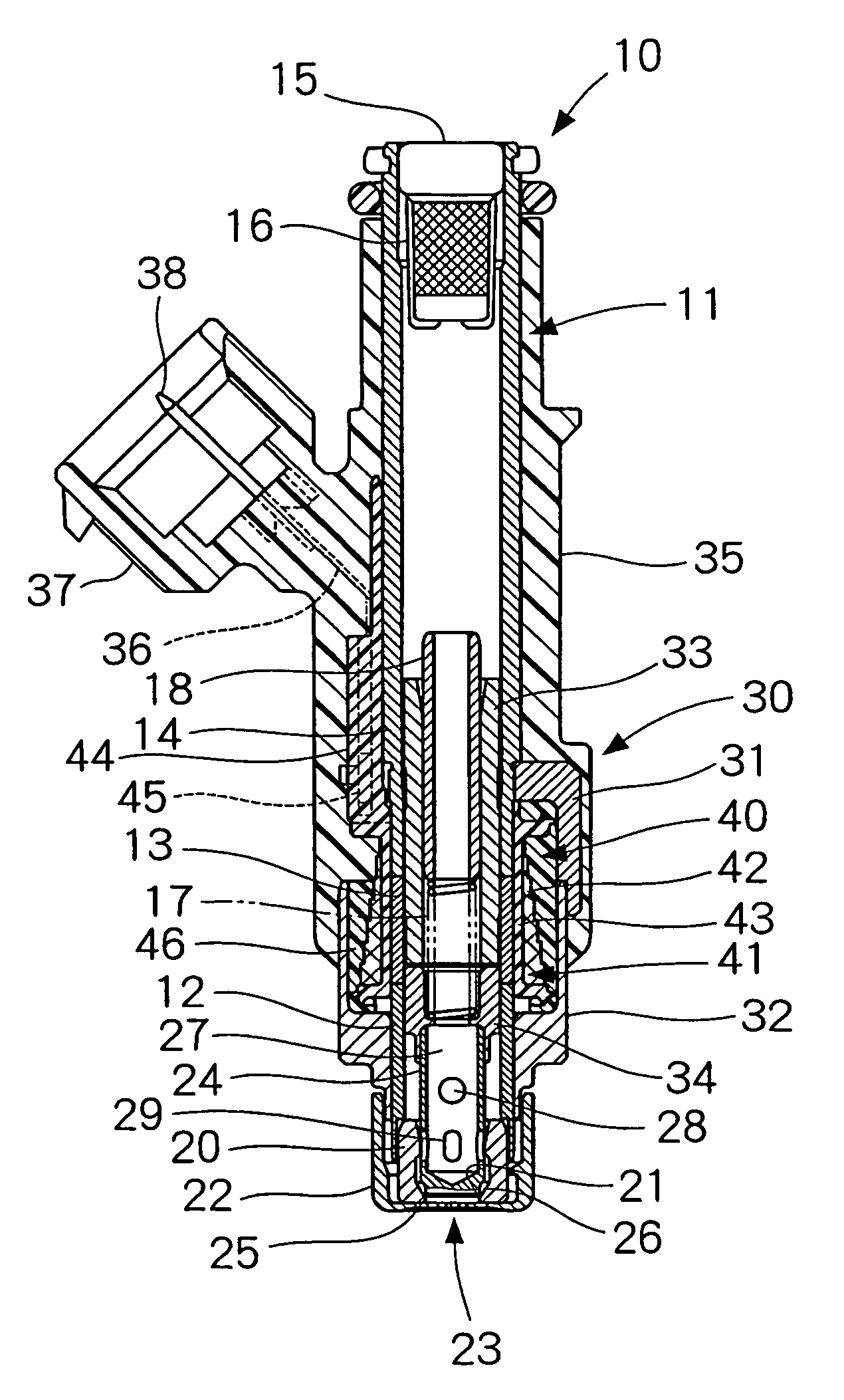
[0021]A fuel injection valve in a first embodiment of the present invention is shown in FIG. 1 (The fuel injection valve is called as ‘Injector’ hereinafter). The injector 10 in the first embodiment injects, for example, a fuel into an intake air provided to a combustion chamber of a gasoline engine. The injector 10 may be used in a direct-gasoline injection engine that directly injects gasoline into the combustion chamber, or may be used in a diesel engine.

[0022]A reception pipe 11 of the injector 10 has a thin-walled cylindrical shape. The reception pipe includes a first magnetic portion 12, a non-magnetic portion 13 and a second magnetic portion 14. The non-magnetic portion 13 prevents magnetic short-circuit between the first magnetic portion 12 and the second magnetic portion 14. The reception pipe 11 has a fuel port 15 on one end. The fuel port 15 receives a fuel from a fuel pump not shown in the figure. The fuel provided to the fuel port 15 flows into the reception pipe 11 thr...

second embodiment

[0045]The injector 10 in a second embodiment of the present invention is shown in FIG. 6. Like parts have like numbers as used in the first embodiment, and descriptions of the like parts are omitted.

[0046]The coil portion 40 has a magnetic member 60 on an outer surface. The magnetic member 60 is made of a magnetic material. The magnetic member 60 has two ends, that is, one end 61 in an axial direction that is in contact with the first magnetic portion 12 of the reception pipe 11, and the other end 62 that is in contact with the second magnetic portion 14. In this manner, the magnetic member 60 is magnetically connected to the first magnetic portion 12 and the second magnetic portion 14 of the reception pipe 11. That is, the magnetic member 60 includes the housing 31 and the holder 32 in the first embodiment in an integrated form. Further, the magnetic member 60 accommodates the coil portion 40 in the body. The magnetic member 60 has an opening in a circumferential direction as shown...


PUM


Abstract

A fuel injection valve includes a valve member for regulating a flow of a fuel to a nozzle hole, a movable core axially slidable in an integrated body with the valve member, a fixed core being faced by an end of the movable core, and a coil portion having an increasing number of winding of a winding wire toward the movable core in a bobbin to have a magnetic attractive force between the movable core and the fixed core upon application of an electric current. The number of winding wire increases toward an end on a movable core side in the coil portion. Therefore, the generated magnetic field increases on the movable core side. In this manner, the magnetic attractive force between the fixed core and the movable core is increased without increasing a cross-section and / or a body of the movable core.

Description

CROSS REFERENCE TO THE RELATED APPLICATION[0001]This application is based on and claims the benefit of priority of Japanese Patent Application No. 2004-265251 filed on Sep. 13, 2004, the disclosure of which is incorporated herein by reference.FIELD OF THE INVENTION[0002]This invention relates to a fuel injection valve that injects a fuel into an internal-combustion engine.BACKGROUND OF THE INVENTION[0003]Conventional fuel injection valves are disclosed in Japanese Patent Documents. The conventional fuel injection valves disclosed therein actuate a valve member by an electromagnetic force between a fixed core and a movable core that slidably moves in an axially reciprocating motion. The electromagnetic force between the fixed core and the movable core can be increased by increasing a cross-sectional area of those cores (refer to a Japanese Patent Document JP-A-H11-500509, and a Japanese Patent Document JP-A-2002-528672). The increased cross-sectional area of the fixed core and the mo...

Claims


Application Information

Patent Timeline
Patent Type & Authority Patents(United States)
IPC IPC(8): F02M51/00
CPCF02M51/0614F02M2200/505F02M61/165F02M51/0682
Inventor YAMAMOTO, SHINSUKE
Owner DENSO CORP
Learn More