Method, a system and a terminal for realizing presenting information interaction of the wireless LAN users

a technology of wireless lan and information interaction, applied in the field of wireless local area network (wlan), can solve the problems of inability to update the information of the presence entity in time, no implementation method for providing the presence information, and inability to acquire the presence information

Inactive Publication Date: 2005-12-01
SNAPTRACK
View PDF7 Cites 44 Cited by
  • Summary
  • Abstract
  • Description
  • Claims
  • Application Information

AI Technical Summary

Benefits of technology

[0017] In the present invention, by steps of setting one or more than one presence information monitoring unit, detecting WLAN client's presence information, and transmitting presence information to PRESENCE service system, the mutual communication between WLAN and the existing PRESENCE service system is implemented. Not only providing the real-time

Problems solved by technology

For those terminals in mobile communication network or Internet, the watcher can acquire the presence information through PRESENCE service system, while for those terminals in WLAN, at present there is no implementing method for providing the presence information and variation information of terminals in WLAN for PRESENCE

Method used


Image

  • Method, a system and a terminal for realizing presenting information interaction of the wireless LAN users
  • Method, a system and a terminal for realizing presenting information interaction of the wireless LAN users
  • Method, a system and a terminal for realizing presenting information interaction of the wireless LAN users

Examples


embodiment 1

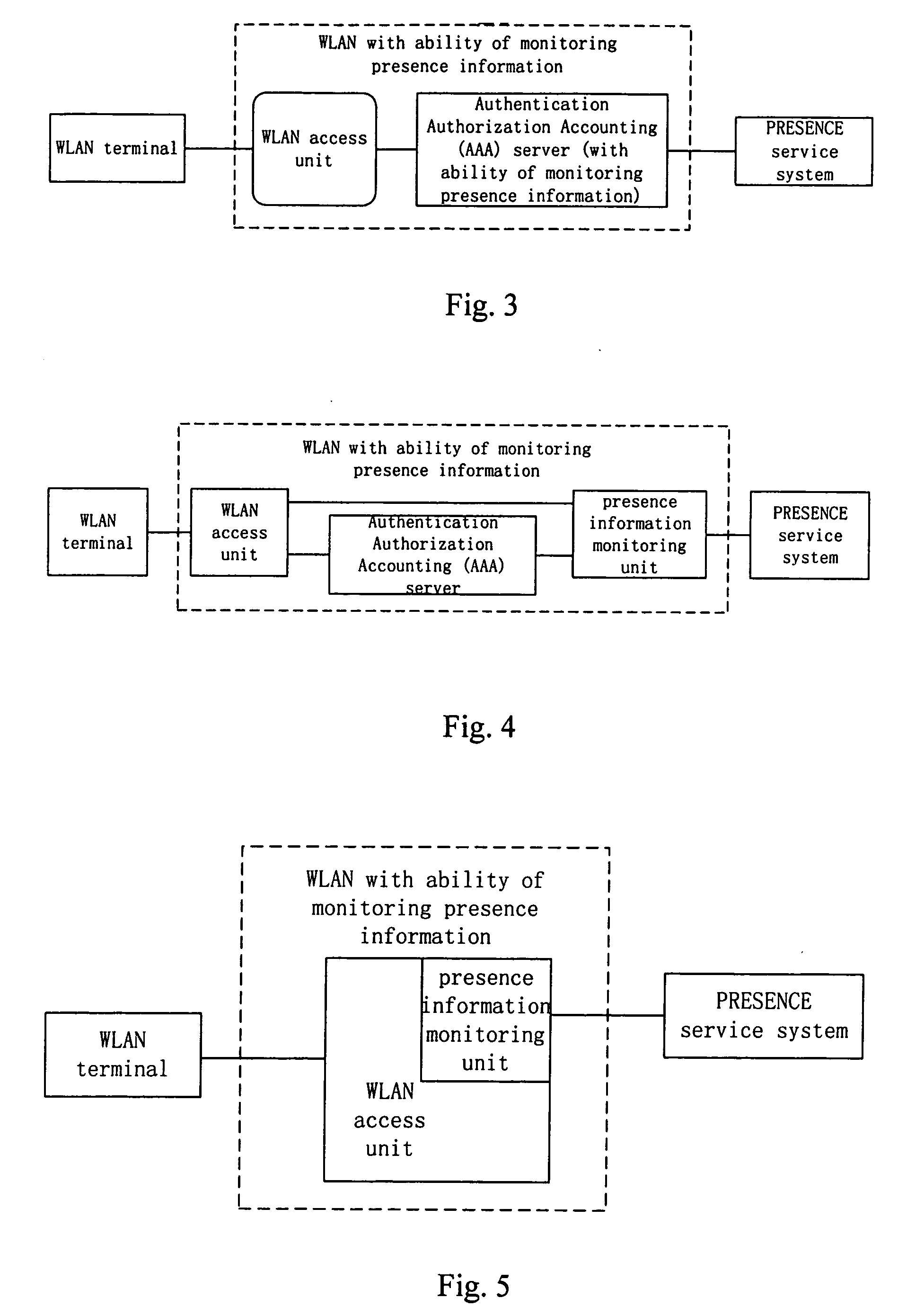
[0040] With reference to FIG. 3, FIG. 3 is the logical structure sketch diagram of embodiment 1 for monitoring and transmitting subscriber's presence information in the AAA server. The presence information monitoring unit can be set inside the AAA server, so that this server is of function to monitor and send connection information to outside PRESENCE service system, and is connected to the PRESENCE service system.

embodiment 2

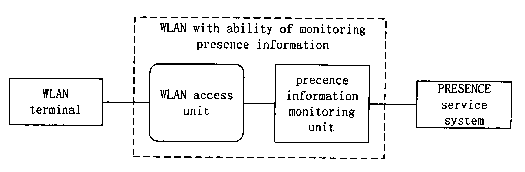
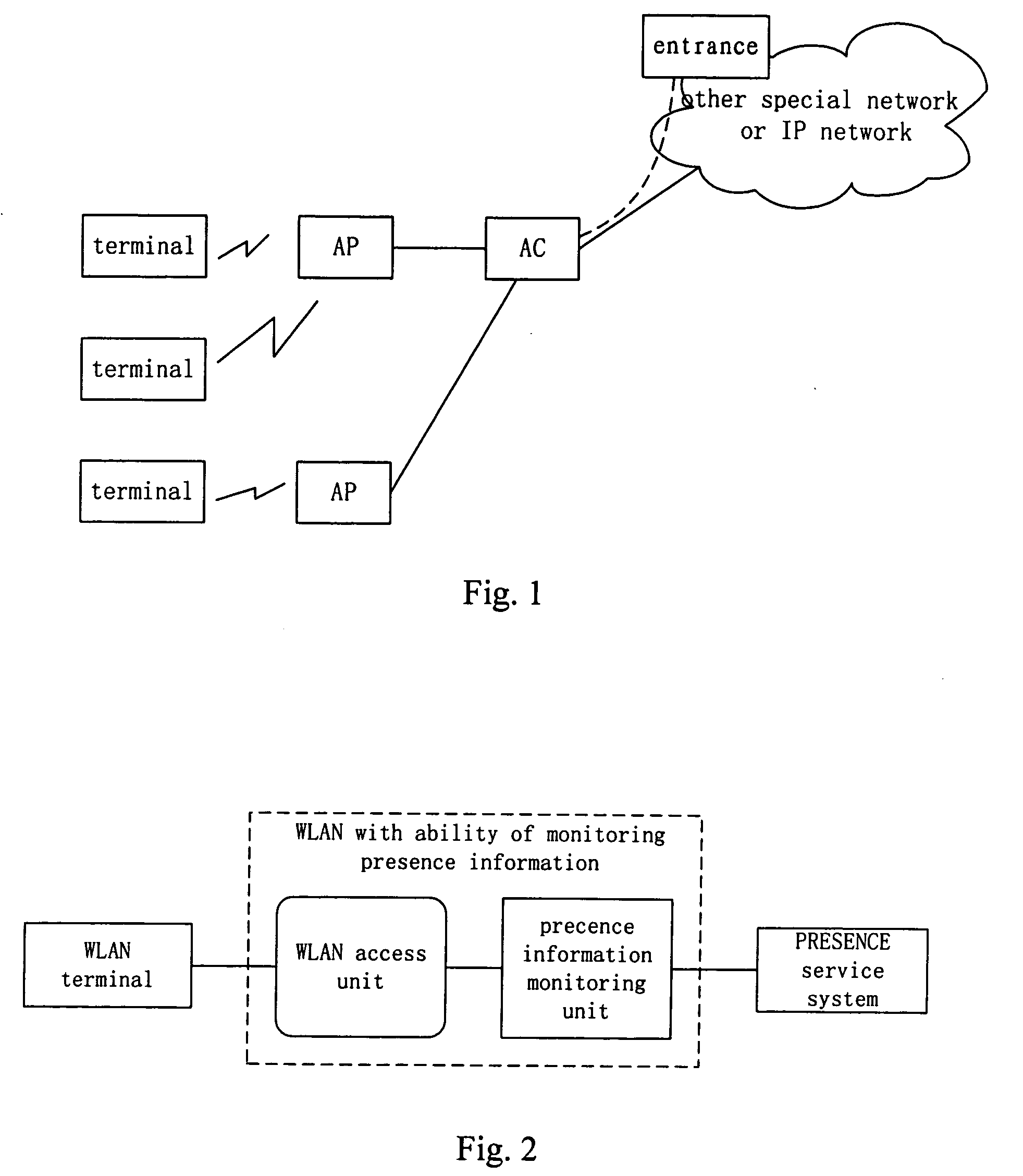
[0041] With reference to FIG. 4, FIG. 4 is the logical structure sketch diagram of embodiment 2 for monitoring and transmitting subscriber's presence information. The presence information monitoring unit is an independent entity, which is located between the AAA server and the PRESENCE service system, and the AAA server is connected to the WLAN access unit; or else, presence information monitoring unit is directly connected to WLAN access unit.

embodiment 3

[0042] With reference to FIG. 5, FIG. 5 is the logical structure sketch diagram of embodiment 3 for monitoring and transmitting subscriber's presence information. The presence information monitoring unit is set in the WLAN access unit and is connected to the PRESENCE service system.

[0043] The said embodiment 1, embodiment 2 and embodiment 3 all implement the objective of the present invention by adding the presence information monitoring unit at WLAN side. The present invention can also implement the object of the present invention by adding the presence information monitoring unit at terminal side.


PUM


Abstract

A method for implementing presence information interaction of WLAN (Wireless Local Area Network) subscriber and the system and terminal thereof, wherein, the method comprises setting one or more than one presence information monitoring unit, detecting the presence information by the presence information monitoring unit, and transmitting this presence information to a PRESENCE service system. The system thereof comprises a presence information monitoring unit, a WLAN network and PRESENCE service system, wherein input of the presence information monitoring unit is connected with WLAN network and the output is connected with PRESENCE service system. The terminal thereof also comprises a presence information monitoring unit, which is connected with PRESENCE service system through WLAN.

Description

CROSS-REFERENCE TO RELATED APPLICATIONS [0001] This application is a continuation of International Application No. PCTCN2003 / 000940 filed on Nov. 7, 2003. This application claims the benefit of Chinese Application Nos. 02148906.8 filed on Nov. 8, 2002 and 02148378.7 filed on Nov. 12, 2002. The disclosures of the above applications are incorporated herein by reference.FIELD OF THE INVENTION [0002] The present invention relates to Wireless Local Area Network (WLAN), especially to a method for implementing presence information interaction of a WLAN subscriber along with a system and a terminal thereof. BACKGROUND OF THE INVENTION [0003] In the mobile communication network or Internet, the subscriber's presence information in PRESENCE service is managed by the network, wherein the presence information comprises subscriber's contact way, current status, subscriber's terminal information, service and service element information etc. The subscriber, subscriber's terminal, service and servi...

Claims


Application Information

Patent Timeline
IPC IPC(8): H04W4/029H04L12/28H04W4/02H04W60/04H04W84/12
CPCH04W4/02H04W60/04H04L67/18H04L67/24H04W84/12H04W4/029H04L67/54H04L67/52H04L12/28
Inventor ZHANG, WENLINLI, ZHIMING
Owner SNAPTRACK
Why Eureka
Try Eureka