Traffic noise barrier system

a technology of noise barrier and attachment, which is applied in the direction of roadway safety arrangements, roads, construction, etc., can solve the problems of no guidance for the evaluation of attachments on or near these barriers, and the walls of noise barrier are usually not designed for vehicle impact,

Active Publication Date: 2005-12-01
BOARD OF RGT UNIV OF NEBRASKA +1
View PDF8 Cites 25 Cited by
  • Summary
  • Abstract
  • Description
  • Claims
  • Application Information

AI Technical Summary

Benefits of technology

[0015] A horizontal centerline of the first longitudinal beam is preferably spaced a distance between about 32 inches to about 44 inches above a terrain surface, and more preferably at 38 inches above the terrain surface. A horizontal centerline of the second longitudinal beam is preferably spaced a distance between about 44 inches to about 74 inches above the terrain surface, and more preferably 60 inches above the terrain surface. The longitudinal barrier may be qualified under National Cooperative Highway Research Program Report No. 350 Test Level 3.
[0016] In another embodiment, a third longitudinal beam is disposed between the path of traffic and the plurality of panels. The third longitudinal beam extends across the plurality of upstanding posts and is spaced above the second longitudinal beam. A horizontal centerline of the third longitudinal beam is preferably spaced a distance between about 100 inches to about 154 inches above the terrain surface, and more preferably about 128 inches above the terrain surface. The longitudinal barrier may be qualified under National Cooperative Highway Research Program Report No. 350 Test Level 4. In one embodiment, the longitudinal barrier has a height greater than or equal to 40 inches above the terrain surface and the first longitudinal beam is omitted.
[0017] Each of the upstanding posts may have a flange extending along substantially an entire height of the upstanding post. The flange extends generally parallel to the panel and forms a gap between opposing, generally parallel surfaces of the flange and the panel. Preferably, the gap is less than or equal to about ½ inch. In one embodiment, an anti-intrusion wedge is disposed within the gap.

Problems solved by technology

Noise barrier walls of this type are suitably sturdy and effective in reducing highway noise; however, such noise barrier walls are usually not designed for vehicle impact.
Problematically, space constraints often require that noise barriers be located closer to the path of traffic.
However, vehicles impacting the otherwise crashworthy traffic barrier may also strike the noise barrier, creating potential hazards to the impacting vehicle and nearby pedestrians.
Although NCHRP Report No. 350 offers guidance for the safety performance evaluation of longitudinal and other traffic barriers, it offers no guidance toward the evaluation of attachments on or near these barriers.
Snagging is when a portion of a vehicle engages a vertical element, such as a post, causing deceleration of the vehicle.
While Keller et al. provide various guidelines for the design of barrier attachments, Keller et al. fail to provide a design for a traffic noise barrier wall that would meet their guidelines.

Method used


Image

  • Traffic noise barrier system
  • Traffic noise barrier system
  • Traffic noise barrier system

Examples


Embodiment Construction

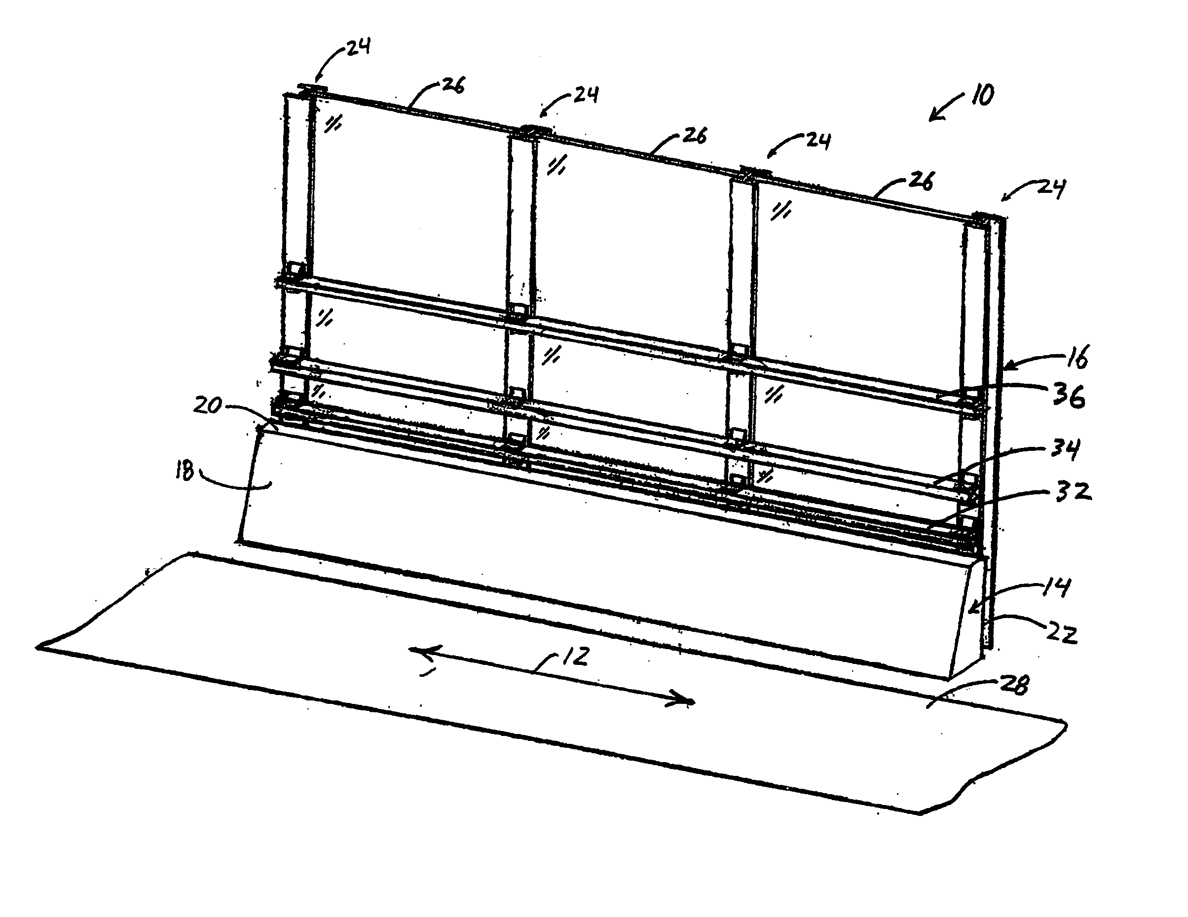
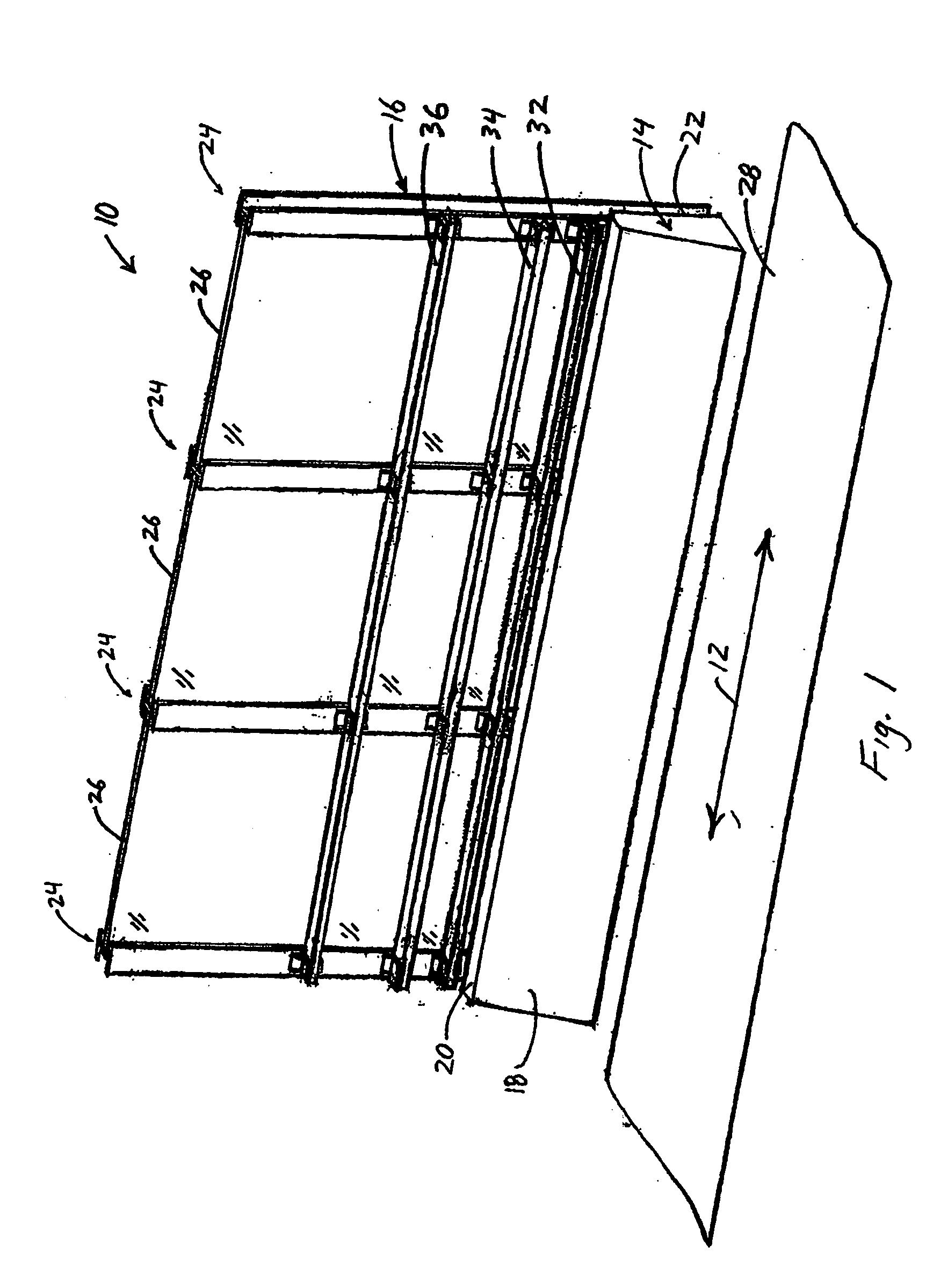
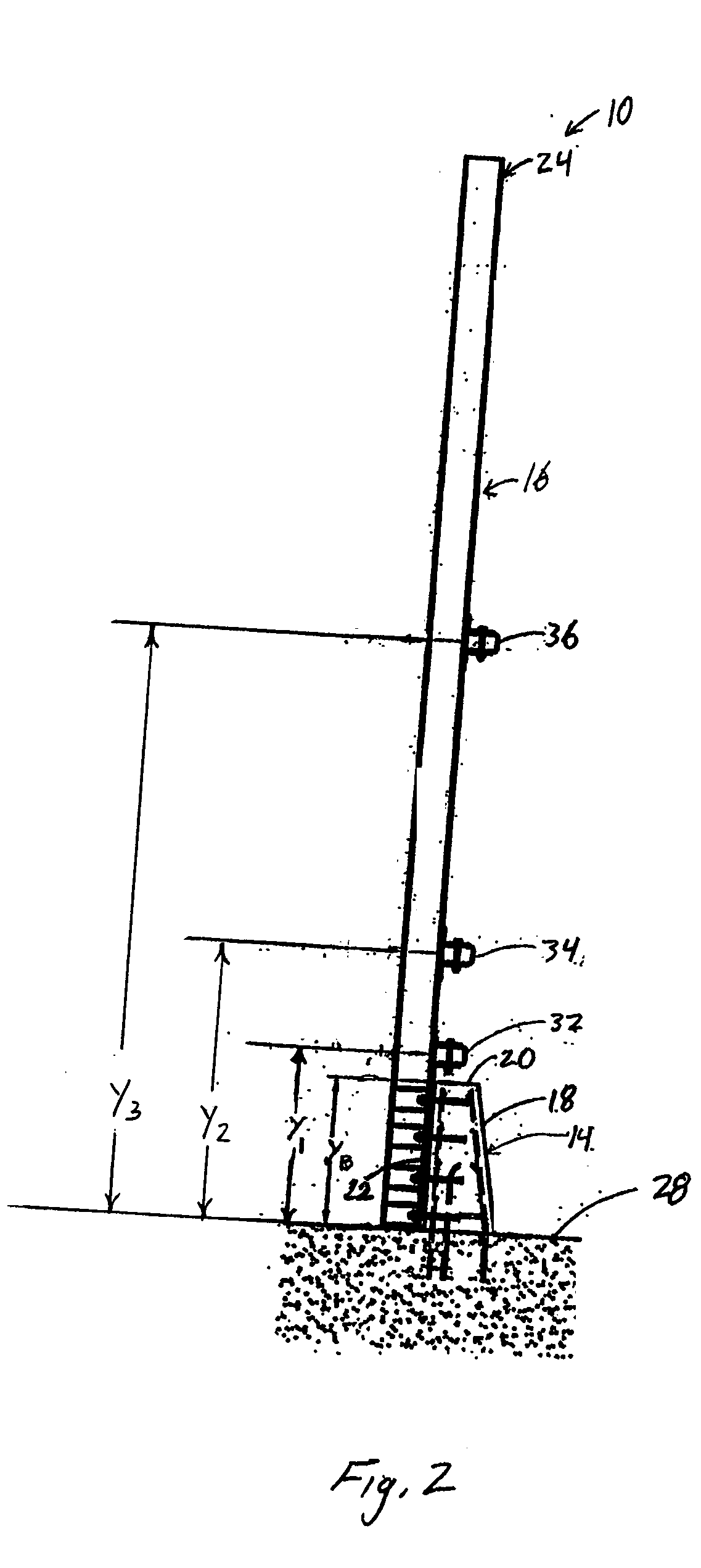
[0031] Referring to FIGS. 1 through 3, a traffic noise barrier system 10 for use alongside a path of traffic 12 is shown. FIG. 1 is a perspective view of the system 10, FIG. 2 is a side elevation view of the system 10, and FIG. 3 is front elevation view of the system 10. The path of traffic 12 may be a roadway, railway, aircraft runway, waterway, parking lot, walkway, bridge and the like. The traffic noise barrier system 10 includes a longitudinal barrier 14 and a traffic noise barrier wall (noise wall) 16 supported by the longitudinal barrier 14. The longitudinal barrier 14 may be any barrier extending longitudinally along at least a portion of the path of traffic 12. For example, the longitudinal barrier 14 may include one or more parapets, median barriers, bridge railings, and the like. The longitudinal barrier 14 includes a front surface 18 facing the path of traffic 12, a top surface 20 adjacent to the front surface 18, and a back surface 22 opposite the front surface 18. In th...


PUM


Abstract

A crashworthy traffic noise barrier system for use alongside a path of traffic, the crashworthy traffic noise barrier system comprises a crashworthy longitudinal barrier extending substantially parallel to the path of traffic and a crashworthy traffic noise barrier wall supported by the longitudinal barrier. The crashworthy traffic noise barrier wall includes a plurality of upstanding posts attached to the traffic noise barrier wall, at least one panel supported between each adjacent pair of posts in the plurality of upstanding posts, and at least one longitudinal beams spaced above a top surface of the longitudinal barrier and extending across the plurality of upstanding posts for redirecting a portion of an errant vehicle away from the at least one panel. The longitudinal beams redirect energy of the errant vehicle away from the panels such that the panels and any fragments of the panels, remain attached to the traffic noise barrier wall. The panels may be transparent and may be reinforced with plastic bands, plastic threads, or a plastic net.

Description

CROSS-REFERENCE TO RELATED APPLICATIONS [0001] The present application claims the benefit of U.S. Provisional Patent Application No. 60 / 559,738 (Attorney Docket No. 102525-100) filed Apr. 6, 2004 and entitled “Traffic Noise Barrier System”, which is incorporated by reference herein in its entirety.BACKGROUND OF THE INVENTION [0002] 1. Field of the Invention [0003] This invention relates to traffic noise barriers. More specifically, this invention relates to a crashworthy traffic noise barrier system for bridge rails and other longitudinal barriers. [0004] 2. Description of the Related Art [0005] Traffic noise barrier walls serve to shield otherwise quiet areas from noise caused by automotive, railway, aircraft, marine, or pedestrian traffic. A typical traffic noise barrier wall is from about 4 to 24 feet in height and runs continuously alongside a selected section of a roadway, railway, aircraft runway, waterway, parking lot, walkway, and the like. [0006] One common design of a traf...

Claims


Application Information

Patent Timeline
Patent Type & Authority Applications(United States)
IPC IPC(8): E01F8/00E01F13/00E01F15/08
CPCE01F15/083E01F8/0017
Inventor HUMPHRIES, ERIC C.BARRATT, STEPHEN D.FALLER, RONALD K.KURZ, KEITH J.SICKING, DEAN L.
Owner BOARD OF RGT UNIV OF NEBRASKA
Why Eureka
Try Eureka