Apparatus and method of controlling saturation of color image

a color image and apparatus technology, applied in the field of apparatus and method of controlling the saturation of color images, can solve the problems of color saturation increase, image severely distorted, and skin color of a character that looks oversaturated and unnatural

Inactive Publication Date: 2005-12-08
SAMSUNG ELECTRONICS CO LTD
View PDF21 Cites 14 Cited by
  • Summary
  • Abstract
  • Description
  • Claims
  • Application Information

AI Technical Summary

Benefits of technology

This patent describes how to adjust the brightness levels of colors in an image based on the content being displayed. By analyzing the signals that make up the image, this technology can determine which parts should be brighter or darker to create a more dynamic and visually appealing display.

Problems solved by technology

The technical problem addressed by this patent is how to effectively control the saturation of colors in an image without causing distortion or loss of detail in either peaks or means, based on different characteristics of the image being processed.

Method used


Image

  • Apparatus and method of controlling saturation of color image
  • Apparatus and method of controlling saturation of color image
  • Apparatus and method of controlling saturation of color image

Examples


Embodiment Construction

[0028] Reference will now be made in detail to the embodiments of the present general inventive concept, examples of which are illustrated in the accompanying drawings, wherein like reference numerals refer to the like elements throughout. The embodiments are described below in order to explain the present general inventive concept while referring to the figures.

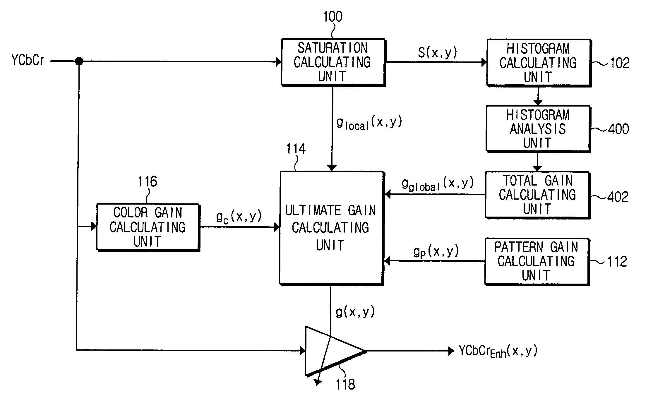
[0029]FIG. 4 is a schematic block diagram illustrating a saturation control apparatus according to an embodiment of the present general inventive concept. The saturation control apparatus includes a saturation calculating unit 100, a histogram calculating unit 102, a histogram analysis unit 400, a total gain calculating unit 402, a pattern gain calculating unit 112, an ultimate gain calculating unit 114, a color gain calculating unit 116, and a saturation control unit 118. Although the saturation control apparatus can include other constitutions besides the above-described units, for convenience's sake only the constitution...


PUM


Abstract

A method of adaptively controlling saturation of an input image according to characteristics of the input image includes a saturation calculating unit to sequentially calculate saturation values of each pixel composing an input image, and to output the calculated saturation values, a histogram analysis unit to accumulate interval values, each interval value corresponding to the saturation value of pixel and being allocated to at least one of two intervals, to calculate a gain corresponding to a cumulative value of each interval, and to output the gain, and a total gain calculating unit to calculate a total gain from the transferred gains of the respective intervals.

Description


Claims


Application Information

Patent Timeline
Owner SAMSUNG ELECTRONICS CO LTD
Why Eureka
Try Eureka