Color imaging apparatus

a color imaging and apparatus technology, applied in the field of color imaging apparatus, can solve the problems of low-frequency coloring, low-frequency coloring, and reduced resolution accordingly, and achieve the effect of suppressing the generation of false colors of high-frequency sections and accurate estimation

Active Publication Date: 2012-11-22
FUJIFILM CORP
View PDF4 Cites 190 Cited by
  • Summary
  • Abstract
  • Description
  • Claims
  • Application Information

AI Technical Summary

Benefits of technology

[0034]According to the present invention, the filter coefficients for the colors of the pixels in the local area extracted from the mosaic image corresponding to the weighted average filters are set so that the proportions of the sums of the filter coefficients of each color in the lines in the horizontal and vertical directions are equal, and the weighted average values of each color are calculated based on the filter coefficients of the weighted average filters and the pixel values of the pixels in the local area extracted from the mosaic image corresponding to the weighted average filters. Therefore, the color ratio or the color difference of the weighted average values of each color in the local area indicates the color ratio or the color difference of the original colors at the pixel position of the target pixel of the local area. As a result, the pixel value of another color can be accurately estimated by interpolating the pixel value of the target pixel based on the color ratio or the color difference of the calculated weighted average values.
[0035]The color ratio or the color difference of the weighted average values of each color in the local area does not change regardless of the type of the frequency input in the horizontal and vertical directions in the local area. Therefore, false determination of color does not occur, and generation of a false color of a high frequency section can be suppressed. The pixel value of another color can be estimated by simple calculation of weighted average and interpolation.

Problems solved by technology

In this case, there is a problem in reproduction characteristics of a high-frequency image signal.
Therefore, there is a problem of low-frequency coloring (color moire) caused by folding of high frequency signals exceeding reproduction bands of the colors and caused by deviation of phases of the colors.
However, although the coloring caused by folding of the high frequency signal can be reduced in the method, there is a problem that the resolution is reduced accordingly.

Method used


Image

  • Color imaging apparatus
  • Color imaging apparatus
  • Color imaging apparatus

Examples


first embodiment

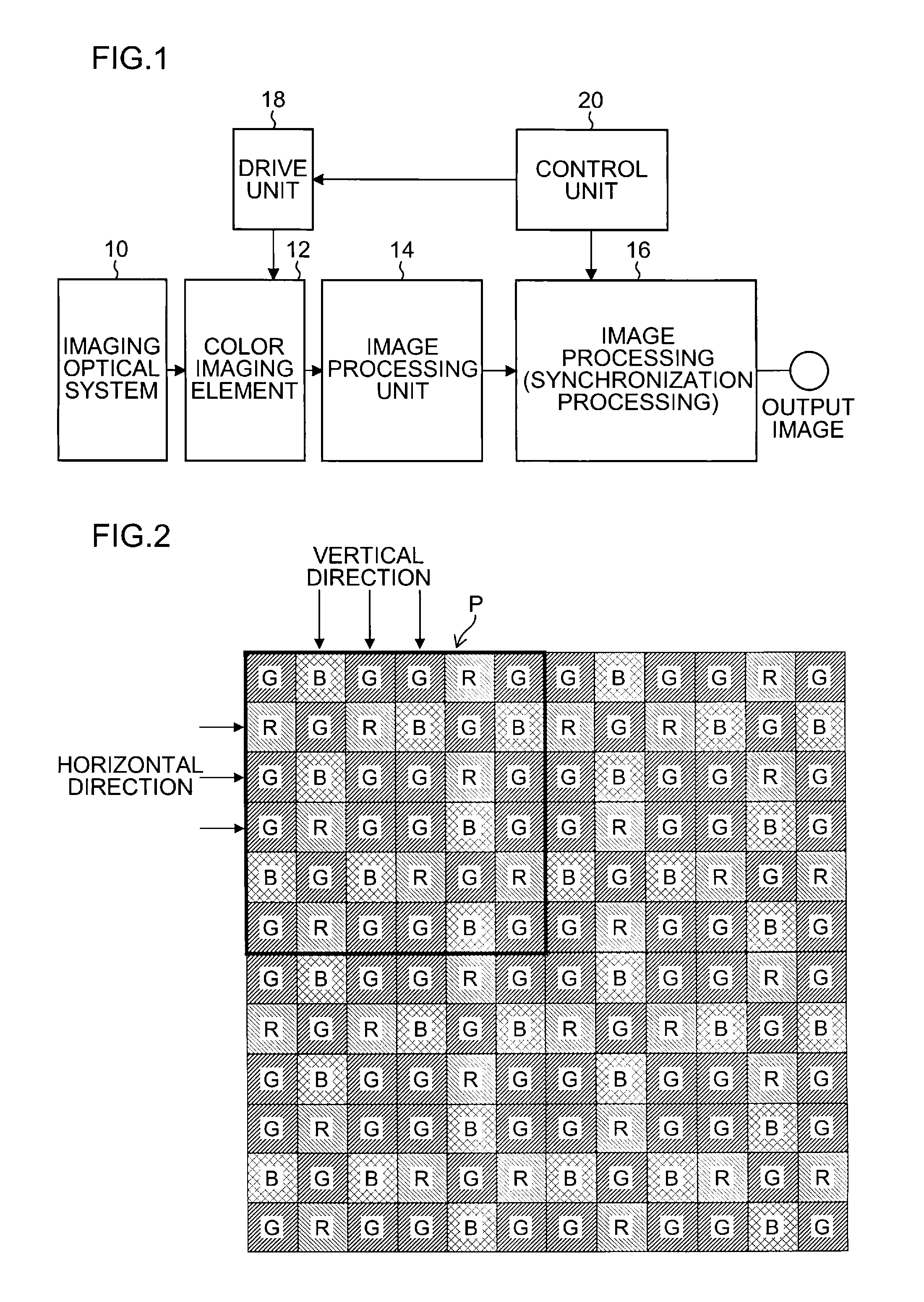
[0051]An imaging optical system 10 images a subject, and an optical image indicating a subject image is formed on a light receiving surface of a color imaging element 12 (color imaging element of a first embodiment).

[0052]The color imaging element 12 is a single-plate color imaging element including: a plurality of pixels (not shown) including photoelectric conversion elements arranged in horizontal and vertical directions (two-dimensional array); and color filters in a predetermined color filter array arranged on light receiving surfaces of the pixels. The color filter array of the color imaging element 12 is characterized by including the filters of all colors of red (R), green (G), and blue (B) periodically arranged in the lines in the horizontal and vertical directions. The details will be described later.

[0053]The photoelectric conversion elements convert the subject image formed on the color imaging element 12 to signal charges corresponding to amounts of incident light. The s...

second embodiment

[0095]{Second Embodiment of Color Imaging Element and Weighted Average Filters}

[0096]FIG. 7 is a diagram showing a second embodiment of the color imaging element and the weighted average filters applied to the present invention. FIG. 7 particularly shows a color filter array of the color filters arranged on the color imaging element and filter coefficients of the weighted average filters applied to the color filter array.

[0097]As shown in FIG. 7, in the color filter array of the color imaging element of the second embodiment, a horizontal line includes RGBRGBRGB . . . , the next horizontal line includes GBRGBRGBR . . . , the next horizontal line includes BRGBRGBRG . . . , and this is repeated.

[0098]More specifically, the color filter array includes the filters of the colors of R, G, and B (R filters, G filters, and B filters) arranged in a predetermined cycle.

[0099]As shown in FIG. 7, the color filter array includes the filters of all colors of R, G, and B arranged in the lines in t...

third embodiment

[0109]{Third Embodiment of Color Imaging Element and Weighted Average Filters}

[0110]FIG. 8 is a diagram showing a third embodiment of the color imaging element applied to the present invention. FIG. 8 particularly shows a color filter array of the color filters arranged on the color imaging element.

[0111]FIG. 9 shows filer coefficients of weighted average filters applied to the color imaging element.

[0112]As shown in FIG. 8, the color filter array of the color imaging element of the third embodiment includes a basic array pattern (pattern indicated by a thick frame) formed by a square array pattern corresponding to 4×4 pixels, and the basic array pattern is repeatedly arranged in the horizontal and vertical directions. Therefore, the color filter array includes filters of R, G, and B colors (R filters, G filters, and B filters) arranged in a predetermined cycle.

[0113]The color filter array includes the filters of all colors of R, G, and B arranged in the lines of the horizontal and ...


PUM


Abstract

A color imaging apparatus comprising: a single-plate color imaging element including color filters arranged on pixels arranged in horizontal and vertical directions where all colors are arranged in each line in the directions; weighted average filters with filter coefficients set in a local area extracted from a mosaic image acquired from the color imaging element corresponding to the weighted average filters so that proportions of sums of the filter coefficients of each color in the lines in the horizontal and vertical directions are equal; a weighted average calculation unit that calculates weighted average values of each color; a demosaicking processing unit that calculates a pixel value of another color at a pixel position of a target pixel of demosaicking processing and that interpolates a pixel value of the target pixel based on a color ratio or a color difference of the calculated weighted average values to calculate the pixel value.

Description

[0001]This application is a continuation application and claims the priority benefit under 35 U.S.C. §120 of PCT Application No. PCT / JP2011 / 067419 filed on Jul. 29, 2011 which application designates the U.S., and also claims the priority benefit under 35 U.S.C. §119 of Japanese Patent Applications No. 2011-042514 filed on Feb. 28, 2011 and No. 2011-162414 filed on Jul. 25, 2011, which applications are all hereby incorporated in their entireties by reference.TECHNICAL FIELD[0002]The present invention relates to a color imaging apparatus, and particularly, to a color imaging apparatus that can suppress generation of color moire.BACKGROUND ART[0003]In a color imaging apparatus including a single-plate color imaging element, an output image from the color imaging element is a RAW image (mosaic image). Therefore, a multi-channel image is obtained by a process of interpolating a pixel of a missing color from a surrounding pixel (demosaicing processing). In this case, there is a problem in...

Claims


Application Information

Patent Timeline
Patent Type & Authority Applications(United States)
IPC IPC(8): H04N9/04
CPCG02F1/133514G06T3/4015H04N9/735H04N9/045H04N23/843H04N25/134H04N23/88
Inventor TANAKA, SEIJI
Owner FUJIFILM CORP
Why Eureka
Try Eureka