
Tampon applicator providing low placement

Inactive Publication Date: 2005-12-08
THE PROCTER & GAMBNE CO
View PDF25 Cites 7 Cited by
  • Summary
  • Abstract
  • Description
  • Claims
  • Application Information

AI Technical Summary

Benefits of technology

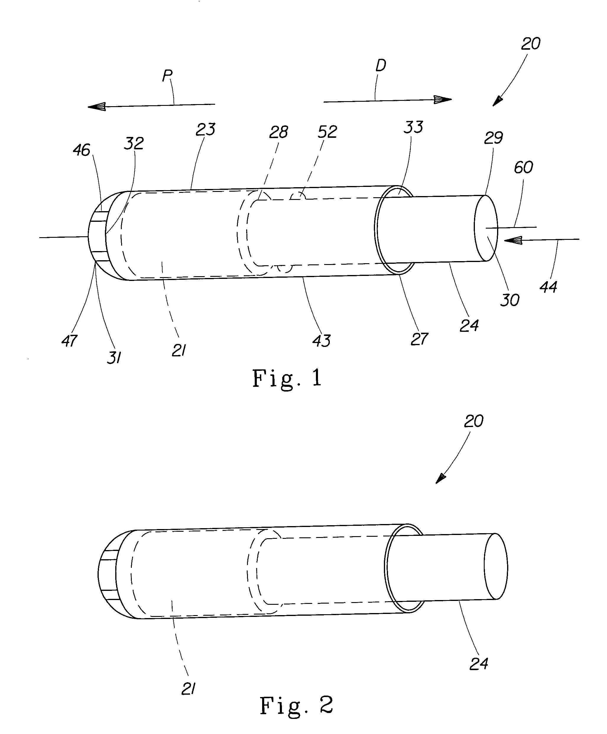
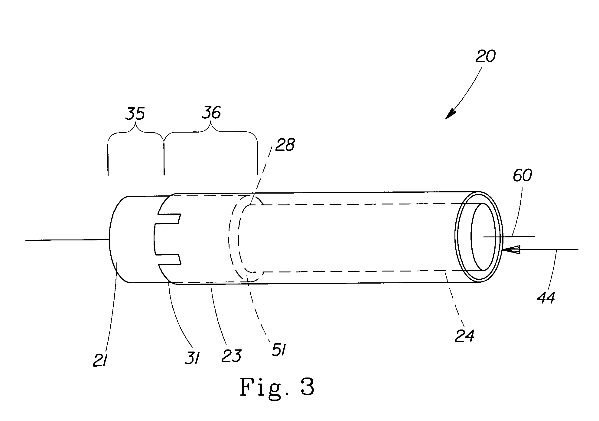
[0007] The present invention encompasses a tampon applicator for positioning a tampon inside a vaginal cavity. The applicator includes an outer member disposed co-axially with an inner member for insertion of the tampon into the vaginal cavity. The inner member is slidable within the outer member wherein a portion of the tampon remains in the outer member when the inner member is fully engaged with the outer member to define a remaining portion of the tampon. The remaining portion of the tampon requires a force of less than about 0.30 N to be removed from the outer member.
[0008] In another embodiment herein, a tampon applicator includes an outer member disposed co-axially with an inner member for insertion of the tampon into the vaginal cavity. The inner member is slidable within the outer member. The outer member comprises an insertion end, an interior surface; and an exterior surface. The inner member comprises an interior surface, an exterior surface, a first end, and a second end. The tampon is at least partially housed within the inner member. A tampon positioning member is disposed within the inner member and co-axially with the tampon for expelling the tampon from the outer member wherein the tampon positioning member is joined to the interior surface of the inner member between the first end and the second end. In addition, a portion of the tampon remains in the inner member when the inner member is fully engaged with the outer member to define a remaining portion of the tampon. The remaining portion of the tampon requires a force of less than about 0.30 N to be removed from the inner member.
[0009] In another embodiment herein, a tampon applicator includes an outer member disposed co-axially with an inner member for insertion of the tampon into the vaginal cavity. The inner member is slidable within the outer member. The outer member comprises

Problems solved by technology

The higher the tampon is placed, the greater the chance of leakage due to the tampon being above the major path of fluid flow.
In addition, if the position of the tampon is too high in the vaginal cavity, the tampon can extend into portions of the vaginal cavity, where, for reasons of the size and mechanical properties of the tampon, the tampon can be negatively affected by the vaginal and surrounding organs, further reducing the tampon coverage of menses flow in the vaginal cavity.
This often causes the tampon to be deflected by the cervix / anterior fomix, resulting in an off-centered position of the tampon, and, thus, result in possible leakage from the vaginal cavity.
When the tampon is placed too low in the vaginal cavity, the too low position of the tampon can cause bodily discomfort to the wearer because of the pressure exerted from the sphincter muscles against the tampon.
Also, if the tampon is placed too low, accidental expulsion of the tampon is a highly undesired risk.

Method used


Image

  • Tampon applicator providing low placement
  • Tampon applicator providing low placement
  • Tampon applicator providing low placement

Examples


Embodiment Construction

[0025] Section A will provide terms which will assist the reader in best understanding the features of the invention but not to introduce limitations in the terms inconsistent with the context in which they are used in this specification. These definitions are not intended to be limiting. Section B will discuss the tampon applicator of the present invention. Section C will discuss the Force Test Method.

A. Terms

[0026] As used herein, the term “tampon” refers to any type of absorbent structure that can be inserted into the vaginal cavity or other body cavities for the absorption of fluid therefrom or for the delivery of active materials, such as medicaments or moisture. A tampon can be straight or non-linear in shape, such as curved along the longitudinal axis.

[0027] Generally, there are two types of tampons. The first type of tampon is a self-sustaining tampon. Tampons are generally “self-sustaining” in that they will tend to retain their general shape and size before use. A typi...


PUM


Abstract

A tampon applicator for positioning a tampon inside a vaginal cavity. The tampon applicator includes an outer member disposed co-axially with an inner member for insertion of the tampon into the vaginal cavity. The inner member is slidable within the outer member wherein at least a portion of the tampon remains in the outer member when the inner member is fully engaged with the outer member to define a remaining portion of the tampon. The remaining portion of the tampon requires a force of less than about 0.30 N to be removed from the tampon applicator. Alternatively, when the inner member is fully engaged with the outer member to define a remaining portion of the tampon, the remaining portion of the tampon requires a force of less than about 0.04 N / mm to be removed from the outer member.

Description

FIELD OF INVENTION [0001] This invention relates to a tampon applicator providing low placement of a tampon within the vaginal cavity. BACKGROUND OF THE INVENTION [0002] Tampon applicators have been used for inserting a tampon into a vaginal cavity to prevent leakage of menstrual fluids or other fluids. In the field of tampon applicators, “push” type tampon applicators are well known. These applicators generally comprise, in a simple form, a pair of coaxial hollow cylinders or tubes. The larger outer tube serves as a vaginal insertion tube and houses a tampon. The smaller inner tube serves as a plunger which ejects the tampon from the outer tube. [0003] It has been recognized that tampon applicators of the type described above have certain deficiencies which can be readily apparent to many users of such devices. In general, the position of the tampon within the vaginal cavity can directly impact the tampon's efficiency of reducing and / or eliminating leakage. For example, conventiona...

Claims


Application Information

Patent Timeline
IPC IPC(8): A61F13/26
CPCA61F13/26
Inventor OSBORN,, THOMAS WARD IIIGANN, DIANA LYNNEBERG,, CHARLES JOHN JR.DANIELS, JACQUELINE ANN
Owner THE PROCTER & GAMBNE CO
Features
  • Generate Ideas
  • Intellectual Property
  • Life Sciences
  • Materials
  • Tech Scout
  • Unparalleled Data Quality
  • Higher Quality Content
  • 60% Fewer Hallucinations
Learn More