System, method and article for enhancing aiming in machine-readable symbol readers, such as barcode readers

a machine-readable symbol and barcode reader technology, applied in the field of automatic data collection, can solve problems such as the turning off of the aiming devi

Inactive Publication Date: 2005-12-15
INTERMEC IP
View PDF36 Cites 20 Cited by
  • Summary
  • Abstract
  • Description
  • Claims
  • Application Information

AI Technical Summary

Benefits of technology

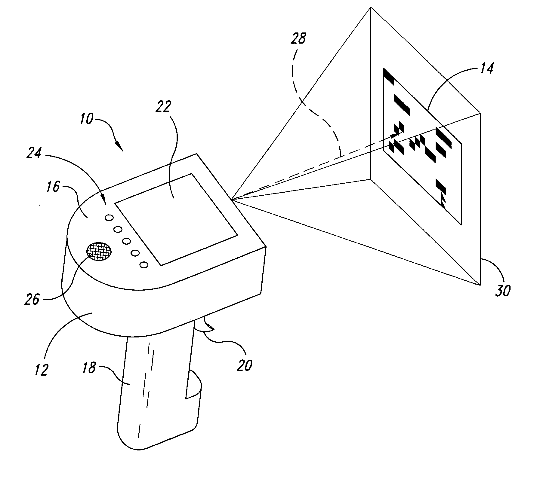
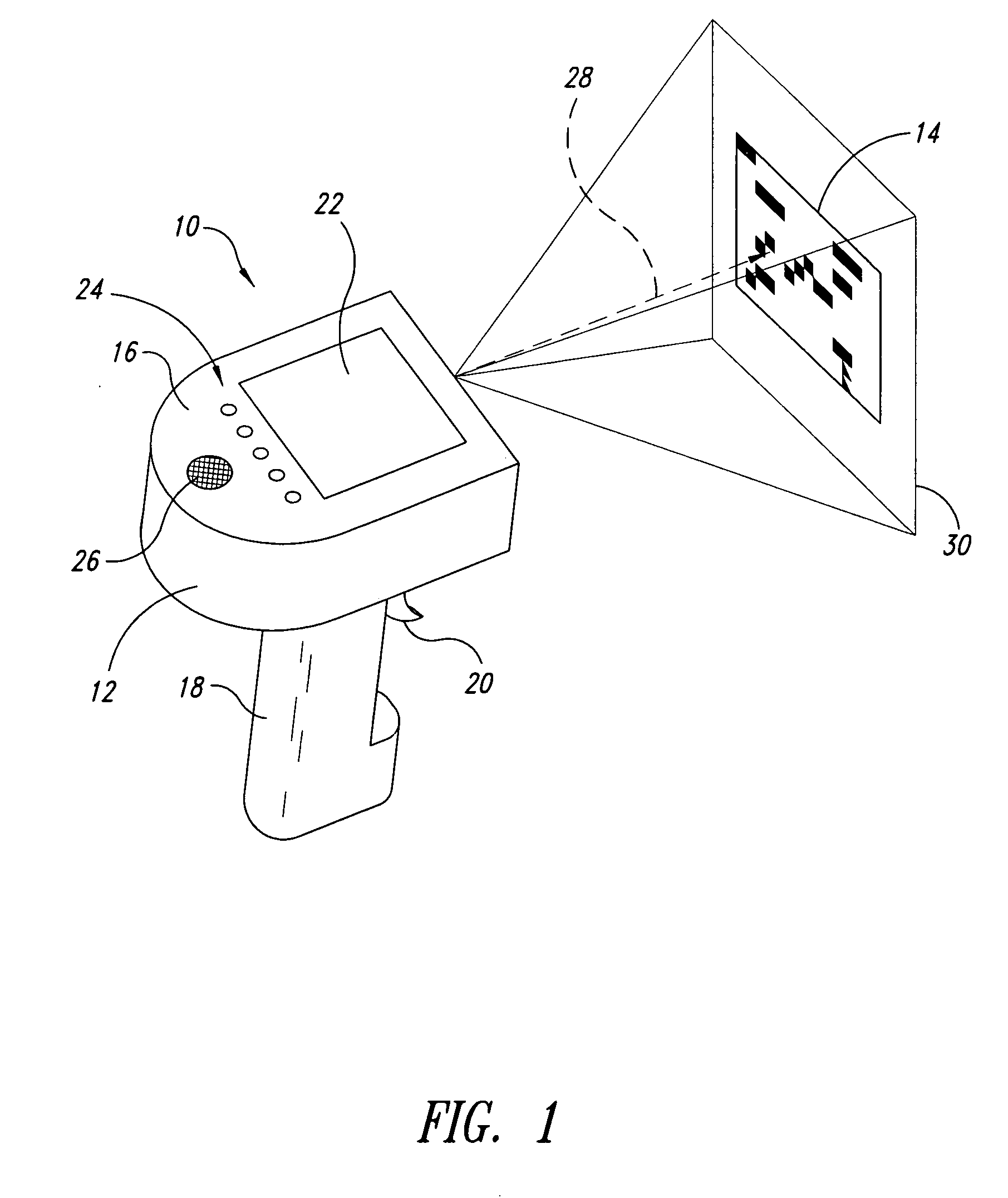
[0008] It is conceived that it would be very advantageous when scanning multiple machine-readable symbols, to have the aiming device active immediately after the previous machine-readable symbol is decoded, or the scan trigger is released, so that the user can easily move on to the next machine-readable symbol without having to depress the trigger again until the reader is aimed at the next machine-readable symbol.

Problems solved by technology

From a user's point of view, one of the most difficult parts to decoding a machine-readable symbol captured with an imager or other machine-readable symbol reader is aiming the reader at the desired symbol.
There are two problems presented by this scenario.
The second problem is that if multiple machine-readable symbols are being acquired and decoded in succession, the aiming device will turn OFF just when it is really desired.

Method used


Image

  • System, method and article for enhancing aiming in machine-readable symbol readers, such as barcode readers
  • System, method and article for enhancing aiming in machine-readable symbol readers, such as barcode readers
  • System, method and article for enhancing aiming in machine-readable symbol readers, such as barcode readers

Examples


Embodiment Construction

[0019] In the following description, certain specific details are set forth in order to provide a thorough understanding of various disclosed embodiments. However, one skilled in the relevant art will recognize that embodiments may be practiced without one or more of these specific details, or with other methods, components, materials, etc. In other instances, well-known structures associated with machine-readable symbol readers, imaging detectors, processors, and illumination systems have not been shown or described in detail to avoid unnecessarily obscuring descriptions of the embodiments.

[0020] Unless the context requires otherwise, throughout the specification and claims which follow, the word “comprise” and variations thereof, such as, “comprises” and “comprising” are to be construed in an open, inclusive sense, that is as “including, but not limited to.”

[0021] Reference throughout this specification to “one embodiment” or “an embodiment” means that a particular feature, struc...


PUM


Abstract

A reader for reading machine-readable symbols such as barcode, area or matrix code, or stack code symbols employs an aiming beam which may continue to provide an indication of an orientation of a field-of-view of the reader for a set interval following a successful decode of a machine-readable symbol. This provides a more intuitive and efficient user interface, allowing a user to quickly aim at a next symbol to be acquired, without inadvertently acquiring and/or decoding an unintended symbol. This may also reduce the number of user actions required to operate the reader, and may simplify the triggering mechanism interface.

Description

CROSS-REFERENCE TO RELATED APPLICATIONS [0001] The application claims benefit under 35 U.S.C. § 119(e) to U.S. provisional patent application Ser. No. 60 / 577,451, filed Jun. 5, 2004.BACKGROUND OF THE INVENTION [0002] 1. Field of the Invention [0003] The disclosure generally relates to the field of automatic data collection (ADC), and more particularly to machine-readable symbol readers, for example, readers for reading machine-readable symbols such as barcode, area or matrix code and / or stacked code symbols. [0004] 2. Description of the Related Art [0005] From a user's point of view, one of the most difficult parts to decoding a machine-readable symbol captured with an imager or other machine-readable symbol reader is aiming the reader at the desired symbol. To aid in this process the machine-readable symbol reader may include a pointer or aiming device that produces a visible aiming beam in response to the user activating a user input device, for example when a user presses a scan ...

Claims


Application Information

Patent Timeline
Patent Type & Authority Applications(United States)
IPC IPC(8): G06K9/24G06K7/10
CPCG06K7/10851G06K2207/1011
Inventor DANT, MICHAEL W.
Owner INTERMEC IP
Why Eureka
Try Eureka