Rapid-firing projectile launcher

a projectile launcher and rapid technology, applied in the field of toys, can solve the problems of slow actual launching, unreliable and expensive indexing arrangements, and unusable mechanisms, and achieve the effects of improving the accuracy of projectile firing, simple and reliable, and enhancing aiming

Inactive Publication Date: 2007-02-15
TSCHECH STEVEN ERIC
View PDF38 Cites 30 Cited by
  • Summary
  • Abstract
  • Description
  • Claims
  • Application Information

AI Technical Summary

Benefits of technology

[0006] Prior art launchers, such, employ various mechanisms for compressing air for powering the projectile launching. Mechanisms such as that taught in U.S. Pat. No. 5,535,729 require the user to pull a lever in a non-linear and rearward motion to launch a projectile. Aside from the complications of this elaborate mechanism, it is found to cause inaccuracy in aiming and shooting the projectiles. The piston and cylinder assembly of the present invention has an axis of translation that is co-axial with the axis of the launching magazine. The force applied by the user to actuate the piston is directly along the line of intended fire. Aside from providing a more simple and reliable mechanism for both the manufacturer and user, this arrangement has been found to enhance aiming and to improve the accuracy of projectiles being fired. Further, because the piston's motion is a short linear stroke, it is possible for a user to quickly and easily operate the piston and cylinder assembly in order to rapidly launch a plurality of sequential projectiles from the magazine without adversely effecting aim and accuracy.
[0007] Accordingly, it is a primary object of the present invention to provide an effective new launcher mechanism for easily and accurately launching a plurality of projectiles from a magazine of a projectile launcher without reloading the launcher.

Problems solved by technology

However, the prior art projectile launchers of this type have included complex, unreliable and expensive indexing arrangements for delivering blasts of compressed air to sequentially arranged projectiles.
Further, prior art firing mechanisms have been less than “user friendly”, resulting in both a slowing of actual launching and fatigue by the user.
Aside from the complications of this elaborate mechanism, it is found to cause inaccuracy in aiming and shooting the projectiles.

Method used


Image

  • Rapid-firing projectile launcher
  • Rapid-firing projectile launcher
  • Rapid-firing projectile launcher

Examples


Embodiment Construction

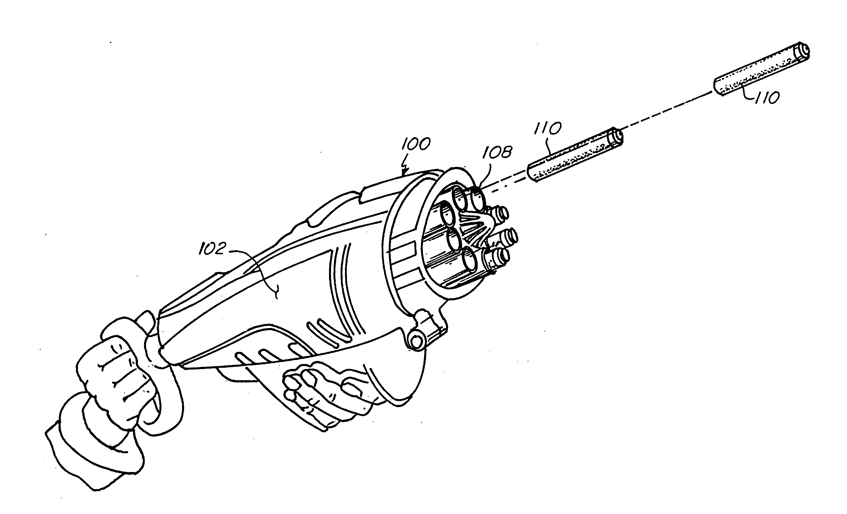
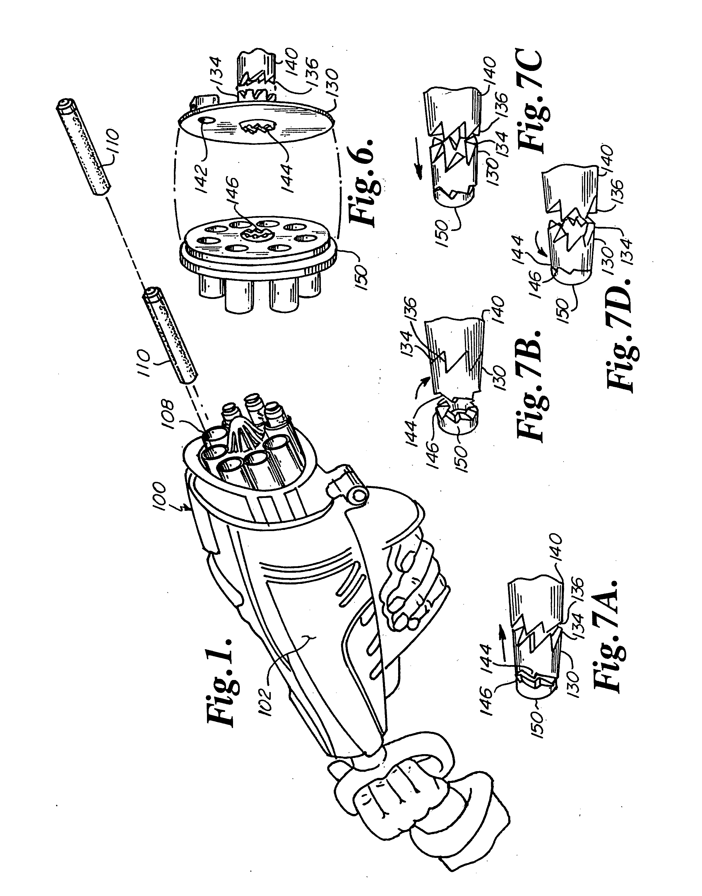
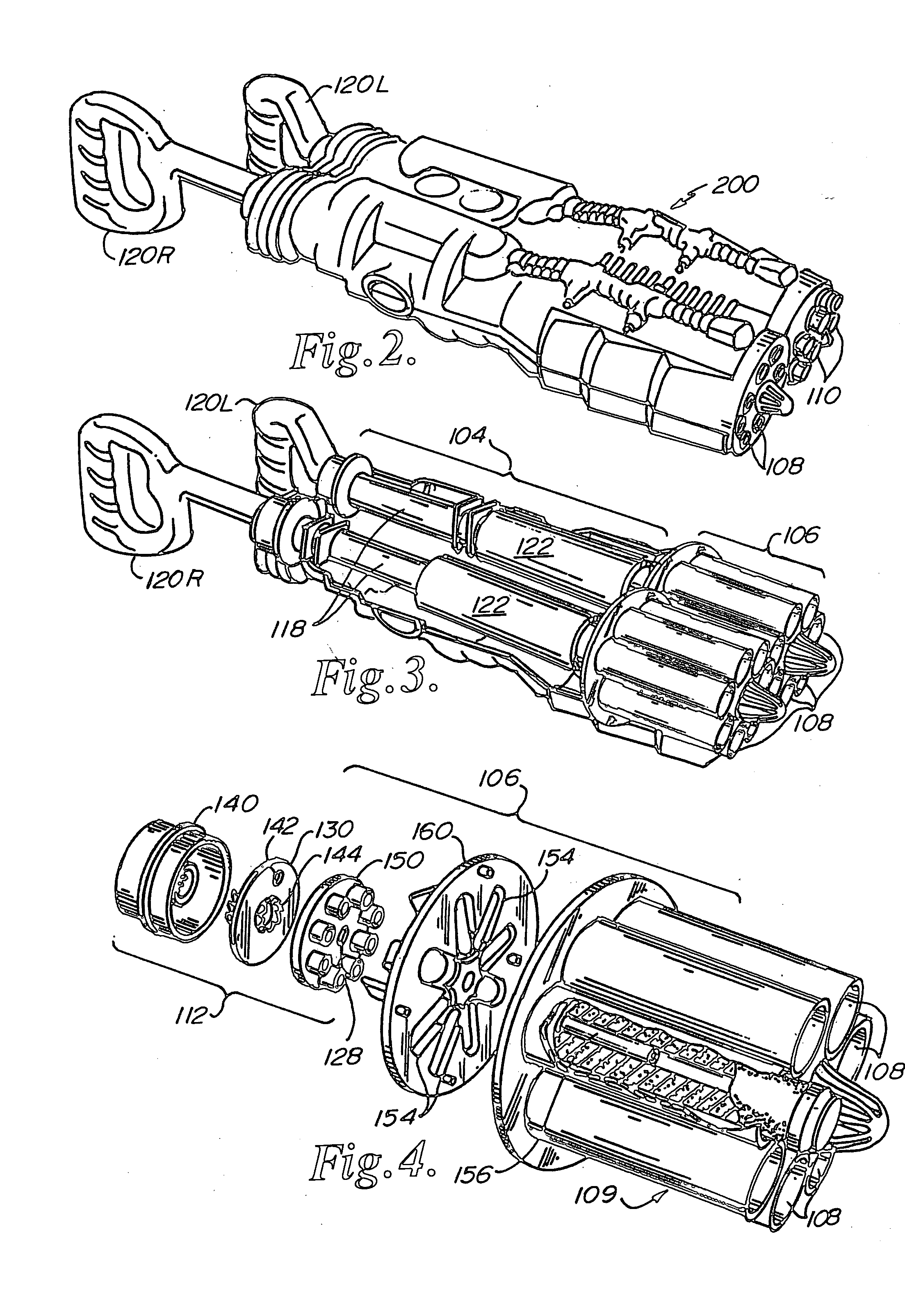
[0018] Referring now to the drawings, two embodiments of the projectile launcher according to the present invention is illustrated in FIGS. 1-8. The launcher 100 of the preferred embodiment is shown in FIG. 1. It comprises a body 102, a piston and cylinder assembly 104, and a launching mechanism 106.

[0019] Launching mechanism 106 has eight equally-spaced launching chambers 108 within magazine 109 for receiving eight projectiles 110, and a manifold assembly 112 for directing air from the piston and cylinder assembly 104 to the launching chambers 108, one at a time and in sequential order upon each successive extension / compression cycle of the piston 118.

[0020] The piston 118 includes a handle 120 at its distal end. The piston is adapted to be moved longitudinally within the cylinder 122 from an extended state (as depicted by the extended position of right-side handle 120R of FIGS. 2 & 3) to a compressed state (as depicted by compressed position of the left-side handle 120L of FIGS....


PUM


Abstract

A projectile launcher has a magazine of launching chambers for holding a plurality of projectiles at the launcher's front end. The projectiles are launchable by the delivery of a blast of compressed air through each chamber's respective air inlet. The air inlets are uniformly spaced in a substantially cylindrical array about the magazine. A piston with a handle is adjacent to the rear end of the launcher body. The piston has a longitudinal axis coaxial with the cylindrical array, and the piston is movable in back-stroke and fore-stroke motions along that axis for inhaling air into the launcher during the back-stroke and exhaling air from the launcher though one of said air inlets in blasts of compressed air during the fore-stroke. A rotatable diverter directs the blasts to one of the air inlets individually and sequentially upon successive backstroke and fore-stroke cycles of the piston.

Description

FIELD OF THE INVENTION [0001] The present invention relates to a toy for shooting or launching projectiles in rapid succession. More specifically, it is a toy gun adapted to shoot a continuous stream of soft projectiles, powered by the compressed air created by a repeated pumping action. In the preferred embodiment, two identical launchers are arranged side-by-side to maximize that number of projectiles the may be launched without reloading. BACKGROUND AND SUMMARY OF THE INVENTION [0002] Projectile launchers that shoot soft foam projectiles by delivering blasts of compressed air thereto have become very popular in recent years. Launchers that are capable of sequentially launching a plurality of projectiles without reloading have been found to have even greater levels of appeal. However, the prior art projectile launchers of this type have included complex, unreliable and expensive indexing arrangements for delivering blasts of compressed air to sequentially arranged projectiles. Fur...

Claims


Application Information

Patent Timeline
Patent Type & Authority Applications(United States)
IPC IPC(8): F41B11/00
CPCF41B11/641F41B11/54
Inventor TSCHECH, STEVEN ERIC
Owner TSCHECH STEVEN ERIC
Why Eureka
Try Eureka