Mounting bracket

a technology for mounting brackets and brackets, which is applied in the field of brackets, can solve the problems of multiple adapters, increased installation costs, and increased installation costs, and achieves the effects of preventing excessive clamping force, reducing installation costs, and facilitating adequate chain tensioning

Active Publication Date: 2011-02-08
BOGEN COMM
View PDF13 Cites 25 Cited by
  • Summary
  • Abstract
  • Description
  • Claims
  • Application Information

AI Technical Summary

Benefits of technology

[0005]It is therefore an object of the invention to provide a mounting bracket that can be used to install a speaker or other object on a variety of surfaces of different sizes. It is another object of the invention to provide a mounting bracket that can be used by one person to install the object in a simple and effective manner.
[0007]The invention provides the means to mount a product on a pole, pipe, column, or the like, and allow the product to be easily aimed in a particular direction, using separate pole adapters. It can also be used on walls without the pole adapters. It should be resistant to weather, wind, and vibration because it will typically be used outdoors. Stainless steel components are preferable. The bracket assembly is suitable for loudspeakers, lighting, signage, displays, monitors, video cameras, etc.
[0008]The invention is specifically designed for one person to install a fairly heavy item. The installer never needs to support the weight of the object and handle attachment hardware simultaneously. Competitive solutions require additional parts, more installers, expensive manufacturing methods, multiple adapters, etc. This system uses a minimal amount of inexpensive but robust components, providing both economic and time based efficiency for the installer.
[0010]For use on poles and the like, the product includes a pole clamp assembly. Two adapter brackets with stepped teeth are attached to the stationary bracket. These adapters are designed for an ideal fit on 1-4″ cylinders, making contact with the cylinder at 4 points each. Larger diameters and irregular shapes can be accommodated, although contact points will likely be reduced to two per adapter. For convenience, a supplied nylon wire tie or other temporary tether is inserted through an opening in the stationary bracket. This can temporarily fasten the stationary bracket with adapters to the pole while clamp components are secured. The clamp is comprised of a length of link chain with a threaded J-hook or hooked rod at each end. These J-hooks pass through aligned slotted openings in the stationary bracket and pole adapters. Wing nuts on the J-hooks provide the means to easily tension the chain adequately without the need for tools, while preventing excessive clamping force. This combination of components fits a wide variety of pole shapes and sizes, produces excellent resistance to rotation, and reduces the likelihood of over tensioning. Additional tension on the clamp components only weakens the system, and wing nuts discourage over-tightening. After installation, the stationary mounting bracket is directly secured to the pole via the chain, hooks, and wing nuts, with the adapters trapped in between. This assembly can be tightened in any position around a pole, providing 360 degrees of horizontal adjustment. This clamp needs only to prevent rotation or slippage and, by nature, chain provides excellent resistance to these forces.
[0011]A speaker mounting bracket can be attached to the adjustable bracket, so that a loudspeaker can be mounted using the assembly according to the invention. The speaker mounting bracket is securely screwed to the adjustable bracket, and the speaker is mounted on the speaker mounting bracket. The assembly of the speaker, speaker mounting bracket and adjustable bracket can then be easily mounted on the stationary bracket to mount the speaker to a pole or other surface.

Problems solved by technology

Competitive solutions require additional parts, more installers, expensive manufacturing methods, multiple adapters, etc.

Method used


Image

  • Mounting bracket
  • Mounting bracket
  • Mounting bracket

Examples


Embodiment Construction

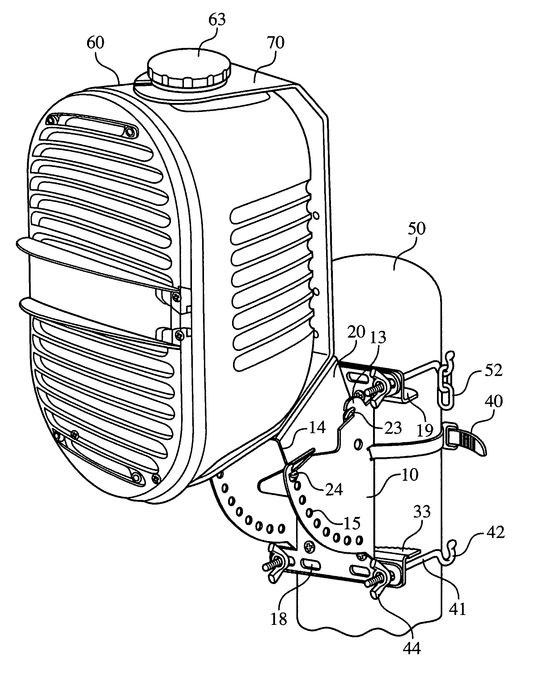
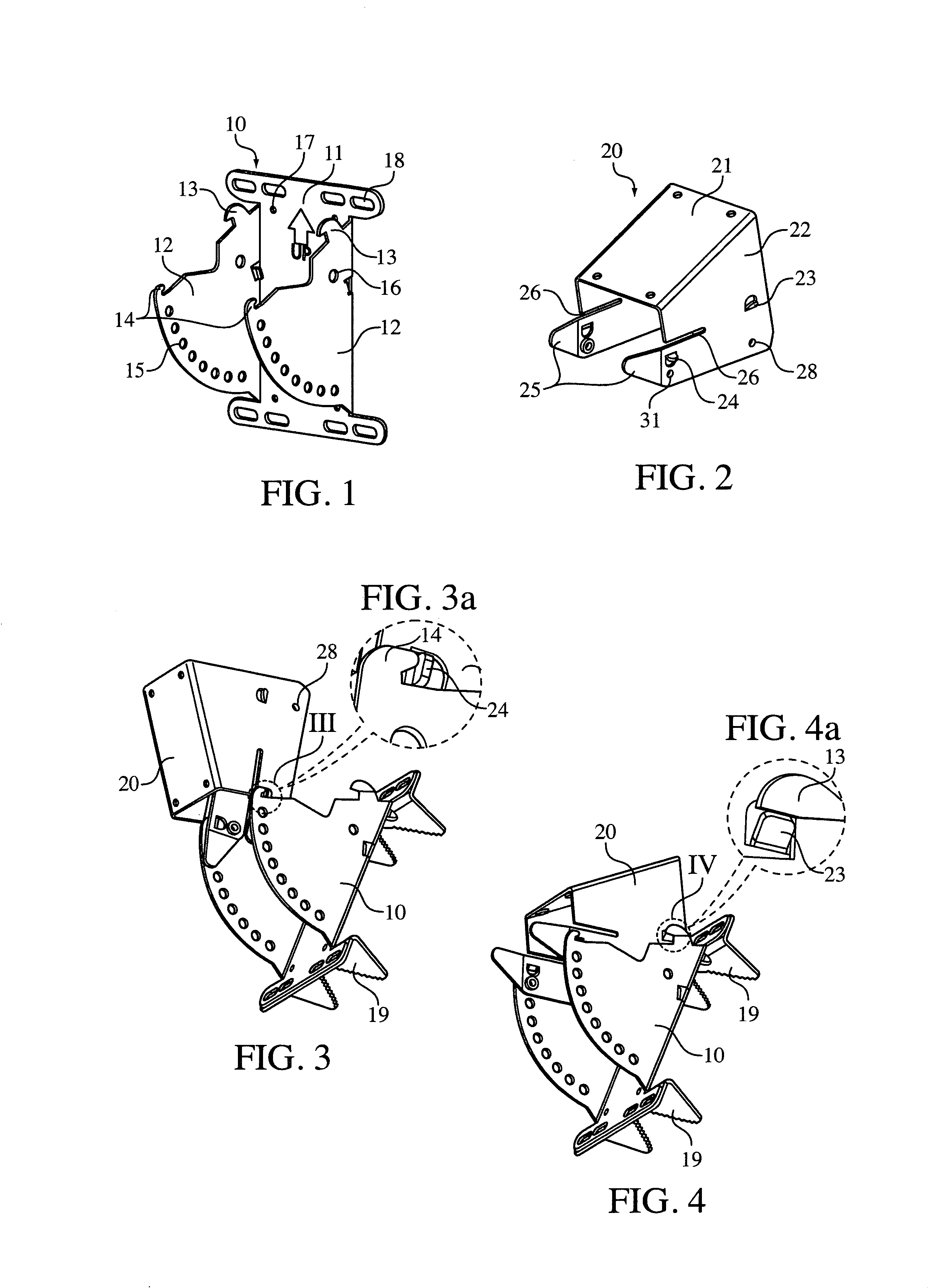
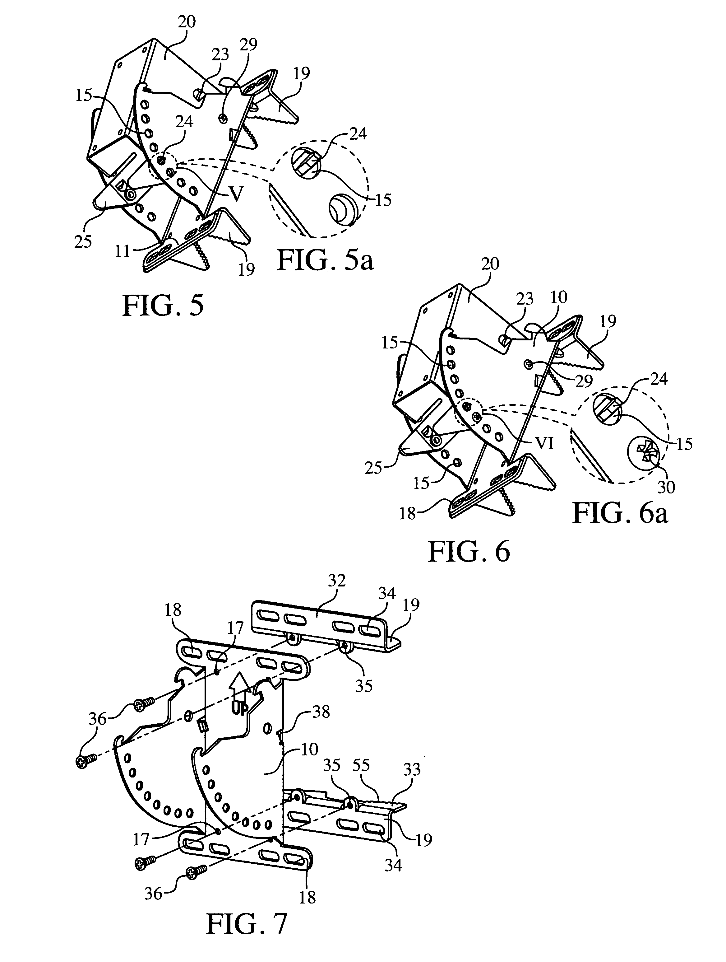
[0029]Referring now in detail to the drawings and, in particular, FIG. 1 shows stationary bracket 10 for use in the assembly according to the invention. Stationary bracket 10 has a flat rear panel 11 and two side walls 12, extending from panel 11. Side walls 12 have an upper edge with hooks 13, 14, and a curved front edge with a series of apertures 15. Side walls 12 also have a rear aperture 16. Rear panel 11 has a plurality of mounting holes 17, for mounting rear panel 11 on a flat surface, and also has slits 18 and supports brackets 19 (shown in FIGS. 3 and 4) for securing stationary bracket 10 to a pole, which will be described in detail below.

[0030]FIG. 2 shows one embodiment of an adjustable bracket 20 for use in the assembly according to the invention. Bracket 20 has a top surface 21, and side walls 22 with flexible wings 25 below a slit 26. Tabs 23 and 24 are disposed along the rear and front areas, respectively, of side walls 22.

[0031]To connect adjustable bracket 20 to stat...


PUM


Abstract

A mounting bracket assembly has a stationary bracket to be mounted on a pole or other surface, and an adjustable bracket to be attached to the object to be mounted. The adjustable bracket is then positioned on the stationary bracket to mount the object on the surface or pole. The adjustable bracket is first mounted on the stationary bracket in a preliminary mounting position using integrated hooks and latches, and then can be easily adjusted to a permanent mounting position and secured with screws.

Description

BACKGROUND OF THE INVENTION[0001]1. Field of the Invention[0002]The invention relates to a bracket for use in mounting speakers or other equipment to a pole, flat surface, or other structure. In particular, the invention relates to a two-part bracket that allows simple mounting of the equipment to the mounting surface by connecting the two parts of the bracket together.[0003]2. The Prior Art[0004]In order to mount a speaker or other object onto a pole, a pipe clamp is commonly used. The pipe clamp contains a U-bolt that is specifically sized for a single pipe diameter. The U-bolt usually has threaded ends for nuts to provide an extreme clamping force against the pole. One disadvantage of this type of system is that it requires a different pipe clamp for each size of pole. Another disadvantage is that the installer is required to hold the speaker or other object in place and to tighten the bolts at the same time. This operation thus usually requires two people for installation.SUMMAR...

Claims


Application Information

Patent Timeline
Patent Type & Authority Patents(United States)
IPC IPC(8): F16M11/00
CPCF16M11/08F16M11/12F16M11/2021F16M13/02F16M13/022H04R1/026F16M2200/024
Inventor NELSON, THOMAS
Owner BOGEN COMM
Why Eureka
Try Eureka