Low impedance layered battery apparatus and method for making the same

a battery and low-impedance technology, applied in the direction of wound/folded electrode electrodes, cell components, sustainable manufacturing/processing, etc., can solve the problems of loss of electrical power, heat dissipation internally within the battery, and the end of the cell is not well integrated into the anod

Active Publication Date: 2005-12-15
LITHIUM WERKS TECH BV +1
View PDF5 Cites 48 Cited by
  • Summary
  • Abstract
  • Description
  • Claims
  • Application Information

AI Technical Summary

Problems solved by technology

One problem encountered in traditional battery designs is that of the electrical impedance of the battery itself, which causes loss of electrical power and dissipation of heat internally within the battery.
Another problem with present battery designs is that the ends of the cells are not well integrated into the anode and cathode terminals usually found at either end of a cylindrical battery design.
Yet another deficiency of present battery designs is their inability to provide good thermal response and heat sink capabilities, especially in high-power applications.
Additionally, present battery designs using collector sheets have not been successful in providing a way to connect a plurality of anode or cathode collectors together.

Method used


Image

  • Low impedance layered battery apparatus and method for making the same
  • Low impedance layered battery apparatus and method for making the same
  • Low impedance layered battery apparatus and method for making the same

Examples


Embodiment Construction

[0024] The following describes in detail one or more embodiments suitable for arriving at the method and apparatus described herein, and should not be taken as exhaustive, inclusive, or limiting.

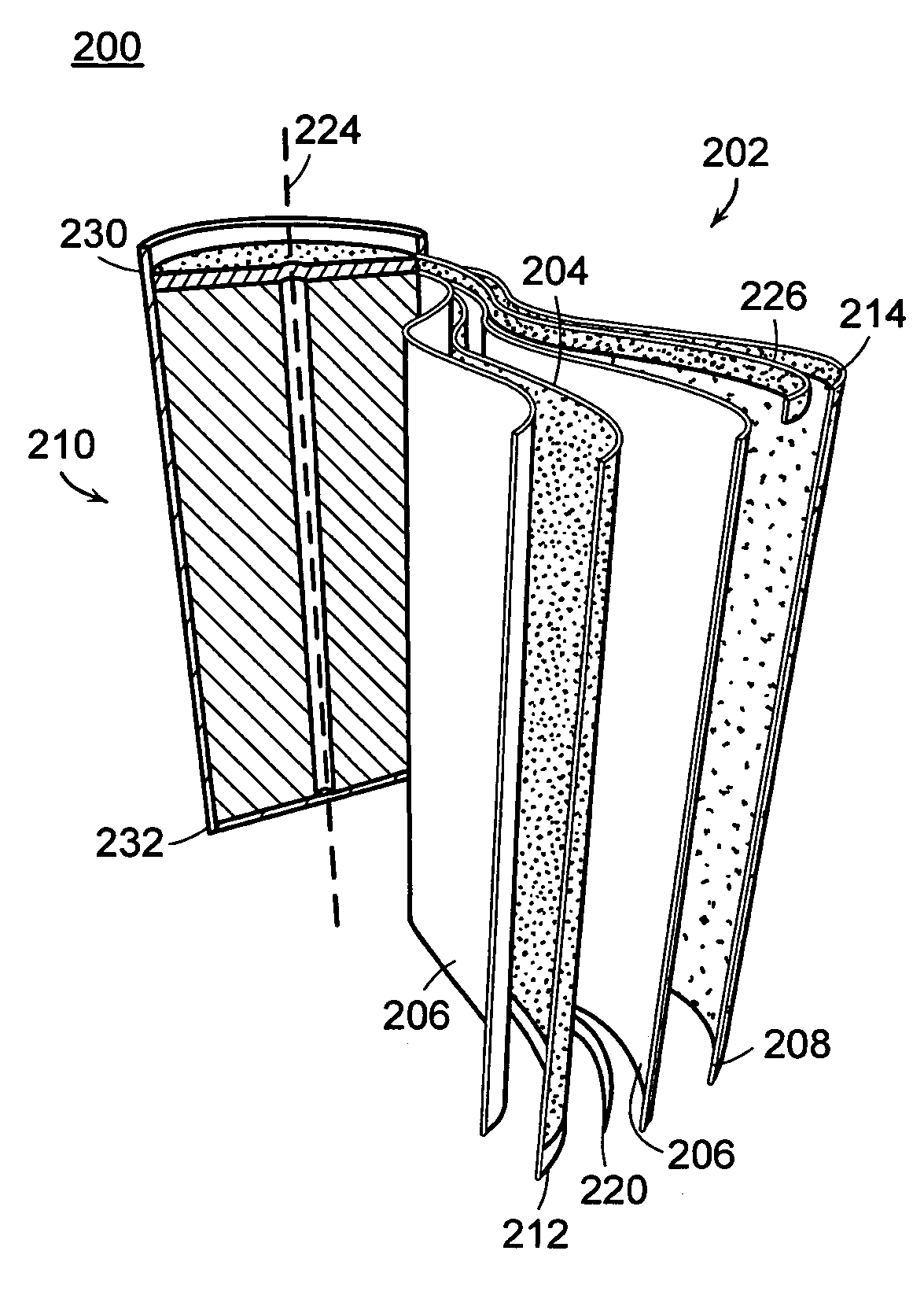
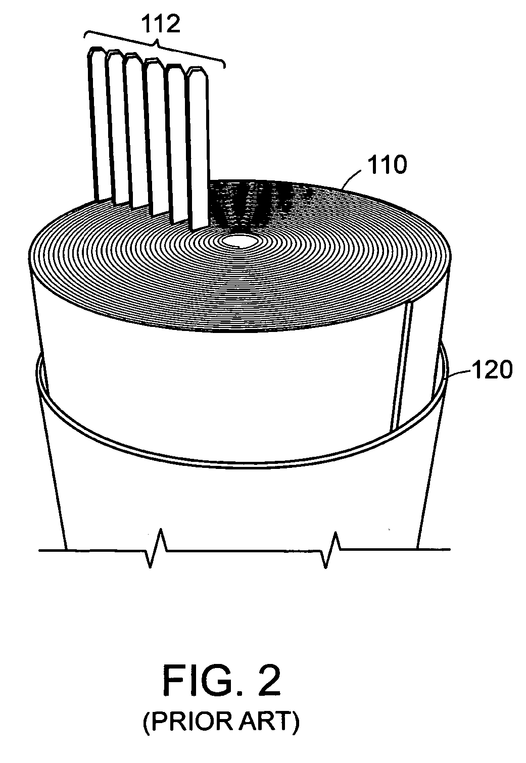
[0025] As mentioned previously, batteries have been formed by co-winding layers of active material (anode, cathode) and separating membrane layers in various geometries as called for by the application at hand. Some are rolled into cylindrical shapes, while others have rectangular or other shaped cross-sections, and are said to have “prismatic” configurations.

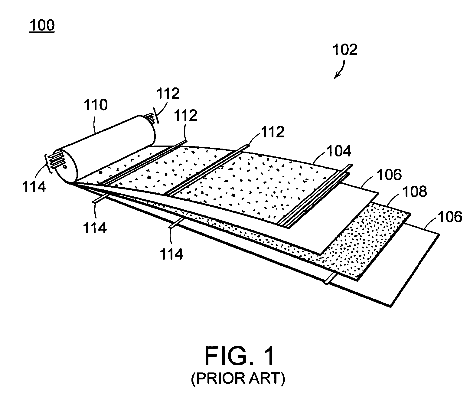
[0026]FIG. 1 shows part of a battery device 100 according to the prior art. Strips or sheets of anode 104 and cathode 108 are separated by separator membranes 106. The composition of anode 104 and cathode 108 depend on the specific type of battery, and include a layer of an electroactive material, e.g., graphite, metal, and other materials on an electrically conductive substrate. The substrate may serve as a current collector. In Li-i...


PUM

PropertyMeasurementUnit
thicknessaaaaaaaaaa
thicknessaaaaaaaaaa
thicknessaaaaaaaaaa

Abstract

An electrochemical storage device is described, and a method for making the same. In some aspects, a guidewire is co-wound with sheet or ribbon-like electrode materials so that contact is made between the guidewire and collector extensions of the electrode materials thereby forming an endcap with low impedance and high thermal sinking capabilities. In one embodiment, the storage device includes a negative electrode sheet have an edge which is substantially free of electrode active material, a positive electrode sheet have an edge which is substantially free of electrode active material, a first conductive guidewire disposed adjacent to the edge of the negative electrode sheet which is substantially free of electrode active material, and a second conductive guidewire disposed adjacent to the edge of the positive electrode sheet which is substantially free of electrode active material. The first conductive guidewire and the edge of the negative electrode sheet which is substantially free of electrode active material define a first electrode endcap and the second conductive guidewire and the edge of the positive electrode sheet which is substantially free of electrode active material define a second electrode endcap. The electrode endcaps are coupled to terminals of the storage device, which are capable of being connected to the terminals of an external circuit.

Description

CROSS-REFERENCE TO RELATED APPLICATIONS [0001] This patent application claims priority to U.S. Provisional Patent Application Ser. No. 60 / 566,888 filed Apr. 30, 2004.TECHNICAL FIELD [0002] The present disclosure relates to construction and use of electro-chemical storage units (batteries). In particular, the disclosure relates to a low-impedance battery apparatus and methods for making and using the same. BACKGROUND [0003] Devices for storing and providing electrical power have been in use for a long time. Generally falling under the descriptor “battery,” such devices include electro-chemical cells and collections of cells that provide an electrical potential between at least a set of terminals. The terminals can be connected to an electrical (e.g. direct current, DC) load to energize or power the load. Batteries include dry cells, wet cells (e.g. lead-acid cells), and other types of units that generally convert a chemically available electromotive force into a current. [0004] Batte...

Claims


Application Information

Patent Timeline
Patent Type & Authority Applications(United States)
IPC IPC(8): H01M6/10H01M6/42H01M10/04H01M10/28H01M10/38H01M10/50H01M50/533H01M50/534H01M50/536H01M50/538H01M50/627
CPCH01M2/26H01M2/263H01M2/361H01M6/10H01M6/42H01M10/04Y02E60/124H01M10/286H01M10/38H01M10/5004H01M10/503H01M10/5044H01M10/5046H01M10/0409H01M10/6551H01M10/643H01M10/655H01M10/613Y02E60/10H01M50/538Y02P70/50H01M50/534H01M50/536H01M50/533H01M50/627H01M10/0431H01M10/0587H01M10/0525H01M50/60
Inventor RILEY, GILBERT N. JR.RIBORDY, JAMES
Owner LITHIUM WERKS TECH BV
Why Eureka
Try Eureka