Heads-up display for displaying surgical parameters in a surgical microscope

a head-up display and microscope technology, applied in the field of head-up displays, can solve problems such as disorienting surgeons

Inactive Publication Date: 2005-12-15
BAUSCH & LOMB INC
View PDF2 Cites 239 Cited by
  • Summary
  • Abstract
  • Description
  • Claims
  • Application Information

AI Technical Summary

Problems solved by technology

However, in order for the surgeon to view the various surgical parameters he must move his gaze from the surgical microscope to the surgical console display screen or listen for audible signals, which may be distracting to the surgeon.

Method used


Image

  • Heads-up display for displaying surgical parameters in a surgical microscope
  • Heads-up display for displaying surgical parameters in a surgical microscope
  • Heads-up display for displaying surgical parameters in a surgical microscope

Examples


Embodiment Construction

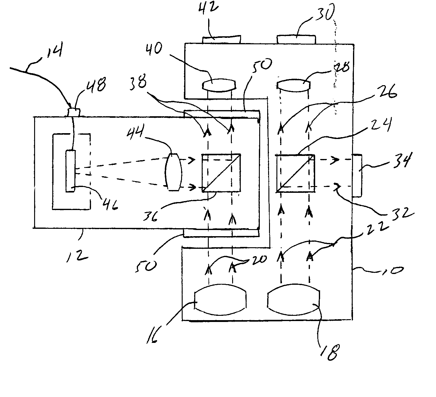
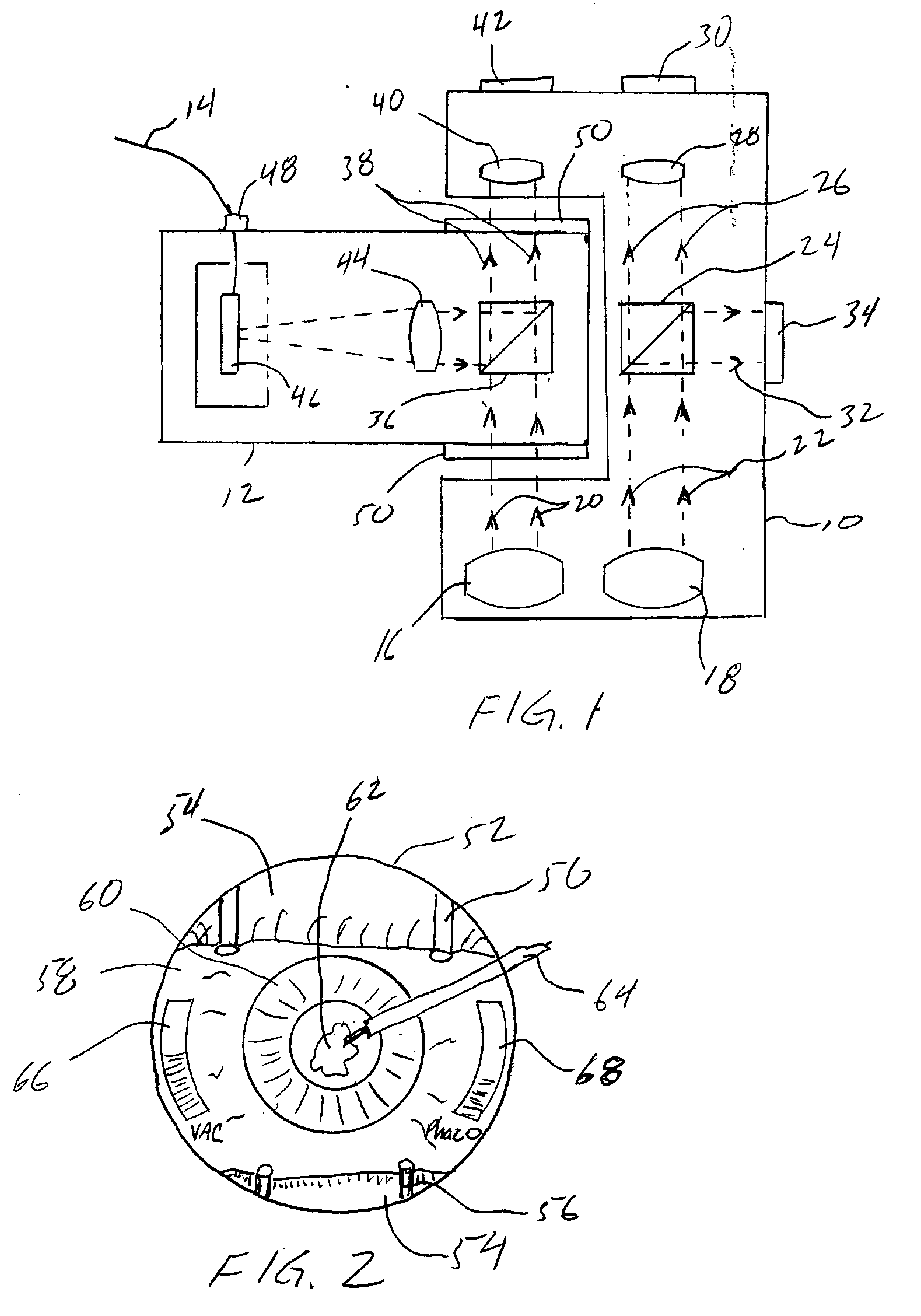
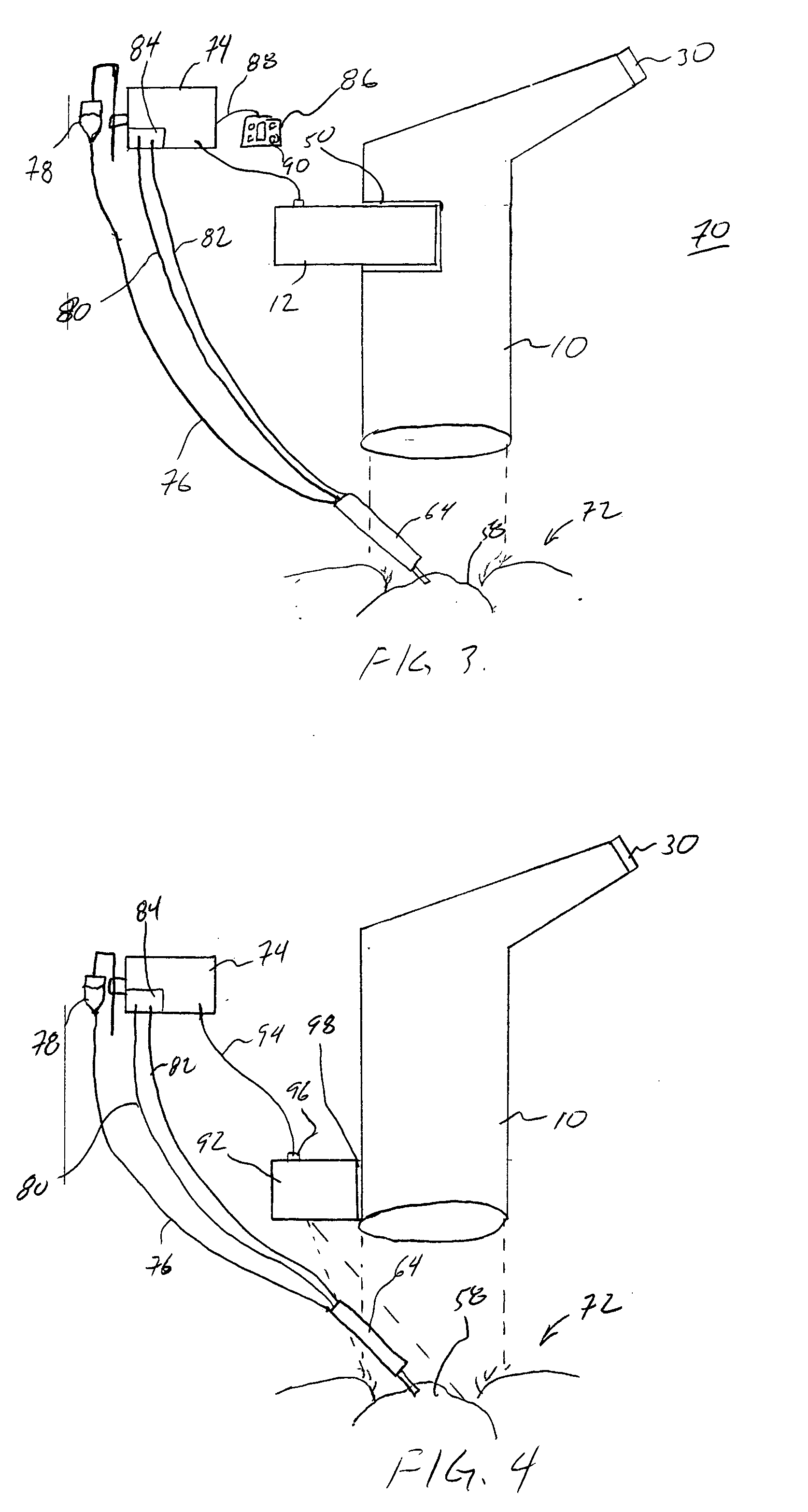
[0012]FIG. 1 shows a surgery-viewing device 10 for observing a surgical site (not shown). A heads-up display 12 is connected to the surgery-viewing device 10 and to a surgical console (not shown) via line 14 for displaying at least one surgical parameter to a user through the surgical viewing device 10.

[0013] Surgery viewing device 10 is preferably a surgical microscope as shown in block diagram form in FIG. 1, but may be other embodiments, such as those described below. Surgery viewing 10 is preferably a typical surgical microscope except that provision is made in the microscope for the attachment of a heads-up display 12 in accordance with the present invention. Microscope 10 observes a surgical site (not shown) through lenses 16 and 18. Culminated light passes through the lenses 16 and 18 in the direction of arrows 20 and 22. The light through lens 18 then passes through beam splitter 24, which splits the light, such that a portion of the light passes through as indicated by arr...


PUM


Abstract

An ophthalmic surgical system 70 includes a surgery-viewing device 10 for observing a surgical site 72. A surgical console 74 controls at least one surgical instrument 64. The surgical console 74 detects certain surgical parameters during surgery. A heads-up display 12 is connected to each of the surgery-viewing device 10 and the surgical console 74 for displaying at least one of the surgical parameters to a user through the surgery-viewing device 10.

Description

BACKGROUND OF THE INVENTION [0001] 1. Field of the Invention [0002] The present invention relates to heads-up displays. More specifically, the present invention relates to ophthalmic surgical systems wherein a heads-up display is connected to a surgical console and to a surgery-viewing device for displaying surgical parameters from the surgical console to the surgery-viewing device. [0003] 2. Description of Related Art [0004] Presently, ophthalmic surgical systems typically have a display, such as an LCD screen or other general used display screen connected to a surgical console. These screens display many important surgical parameters to a user, such as phacoemulsification energy level, vacuum level, or other settings of the surgical equipment, which the surgeon must be aware of. In addition, a surgeon typically performs ophthalmic surgery through the use of a surgery-viewing device, such as a surgical microscope. [0005] The microscope allows the surgeon to properly view the relati...

Claims


Application Information

Patent Timeline
Patent Type & Authority Applications(United States)
IPC IPC(8): A61B17/00A61B19/00A61F9/007A61F9/008G02B21/00G02B27/01
CPCA61B19/52A61B19/5212A61B19/5223A61B2017/00199G02B27/0101A61F2009/00872G02B21/0012G02B27/01A61F9/008A61B90/20A61B90/36A61B90/361
Inventor MCCARY, BRIAN DOUGLAS
Owner BAUSCH & LOMB INC
Why Eureka
Try Eureka