
Annuloplasty prostheses with improved anchoring structures, and related methods

a technology of anchoring structure and annuloplasty, which is applied in the field of annuloplasty prostheses with improved anchoring structure, can solve the problems of insufficient strength of fabric cover to resist stretching or to prevent the sutures from tearing out of the fabric, and the prosthesis may not be effective as desired

Inactive Publication Date: 2005-12-15
ST JUDE MEDICAL LLC
View PDF64 Cites 100 Cited by
  • Summary
  • Abstract
  • Description
  • Claims
  • Application Information

AI Technical Summary

Benefits of technology

[0003] An annuloplasty prosthesis in accordance with the invention is less than a full ring. It is, however, curved to follow a portion of the annulus of a heart valve such as a mitral or tricuspid valve. For example, the prosthesis may be C shaped or U shaped. The prosthesis includes an elongated structural member that basically gives the prosthesis its shape. This structural member has at least two surface portions that are transverse to adjacent portions of the surface of the structural member. These two transverse surface portions are spaced from one another along the length of the structural member....

Problems solved by technology

Because such a prosthesis is less than a full ring, it can be difficult to implant the prosthesis so that the tissue to which it is secured cannot spread (or continue to spread) along the length of the prosthesis.
However, the fabric cover may not be strong enough to resist stretching or to prevent the sutures from tearing out of the fabric, especially near one or both ends of the prosthesis; in which cases the tissue may be able to move (or continue to move) relative to the prosthesis, e.g., by spreading along the length of the prosthesis.
Because it is often an objective of the prosthesis to reverse or prevent such tissue movement, the prosthesis may be less effective than desired.

Method used


Image

  • Annuloplasty prostheses with improved anchoring structures, and related methods
  • Annuloplasty prostheses with improved anchoring structures, and related methods
  • Annuloplasty prostheses with improved anchoring structures, and related methods

Examples


Embodiment Construction

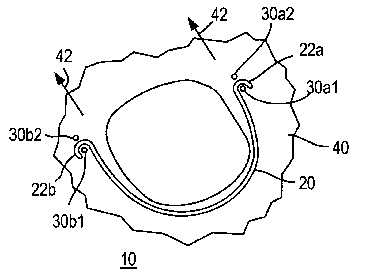
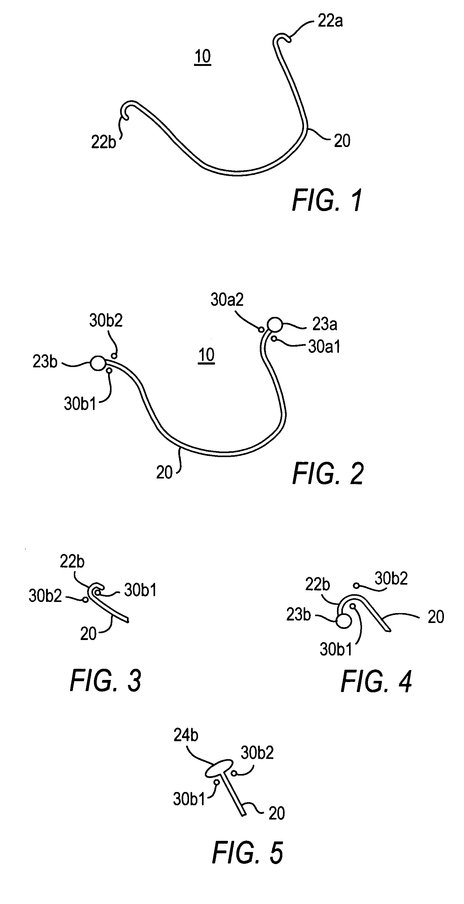
[0016] As is shown in FIG. 1, an illustrative embodiment of an annuloplasty prosthesis 10 in accordance with the invention includes a structural member 20 that is longitudinal but curved along its length. In addition, structural member 20 has attachment hooks 22a and 22b at respective opposite ends of its length. Structural member 20 is preferably substantially rigid or semi-rigid. At the very least, structural member has sufficient rigidity to cause prosthesis 10 to generally hold a predetermined shape, although perhaps with some flexibility (i.e., ability to move or flex with the tissue to which the prosthesis has been sutured when it is implanted in a patient). A rigid prosthesis exhibits little or no movement or flexing in response to attempted normal movement of adjacent tissue. A semi-rigid prosthesis exhibits more movement or flexing in response to attempted normal movement of adjacent tissue. Prostheses in accordance with this invention may be either rigid or semi-rigid in t...


PUM


Abstract

An annuloplasty prosthesis is less than a complete ring (e.g., it may be C-shaped or U-shaped). The prosthesis has a structural member that basically gives the prosthesis its shape. The structural member is provided with surface portions that are transverse to adjacent portions of the surface of the structural member. At least two of these transverse surface portions are spaced from one another and face toward one another along the length of the structural member. Sutures that are used to implant the prosthesis and that are respectively adjacent to these two transverse surface portions are thereby prevented from moving farther apart along the length of the prosthesis.

Description

[0001] This application claims the benefit of U.S. provisional patent application 60 / 579,737, filed Jun. 14, 2004, which is hereby incorporated by reference herein in its entirety.BACKGROUND OF THE INVENTION [0002] Annuloplasty prostheses that are less than completely annular are well known as is shown, for example, by Carpentier U.S. Pat. No. 3,656,185. Because such a prosthesis is less than a full ring, it can be difficult to implant the prosthesis so that the tissue to which it is secured cannot spread (or continue to spread) along the length of the prosthesis. A structural member of the prosthesis may be covered with a soft fabric cover. The prosthesis may be sutured into the patient by sutures that pass through the fabric cover and also through adjacent tissue. However, the fabric cover may not be strong enough to resist stretching or to prevent the sutures from tearing out of the fabric, especially near one or both ends of the prosthesis; in which cases the tissue may be able ...

Claims


Application Information

Patent Timeline
IPC IPC(8): A61F2/24
CPCA61F2/2445
Inventor LIM, JYUE BOON
Owner ST JUDE MEDICAL LLC
Features
  • Generate Ideas
  • Intellectual Property
  • Life Sciences
  • Materials
  • Tech Scout
  • Unparalleled Data Quality
  • Higher Quality Content
  • 60% Fewer Hallucinations
Learn More