
User definable interface system and method

a user interface and user-defined technology, applied in the field of user interfaces, can solve the problems of large amount of data that is available to the user of a modern state-of-the-art data processing system, often becoming overwhelming in magnitude and complexity, time-consuming, less efficient and confusing user interface, etc., and achieve the effect of reducing the commute of cursors

Inactive Publication Date: 2005-12-15
CHANGE TOOLS
View PDF86 Cites 423 Cited by
  • Summary
  • Abstract
  • Description
  • Claims
  • Application Information

AI Technical Summary

Benefits of technology

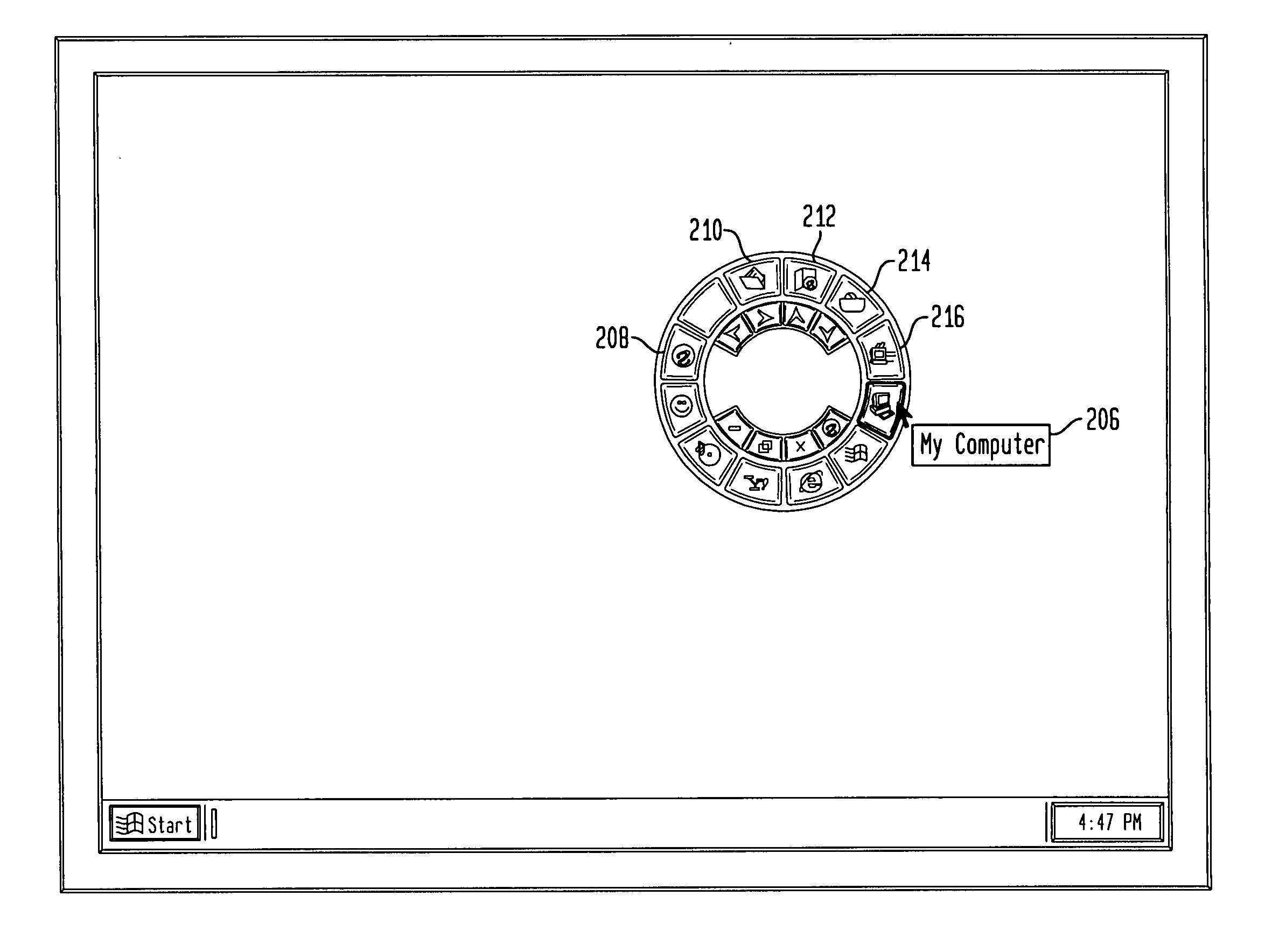
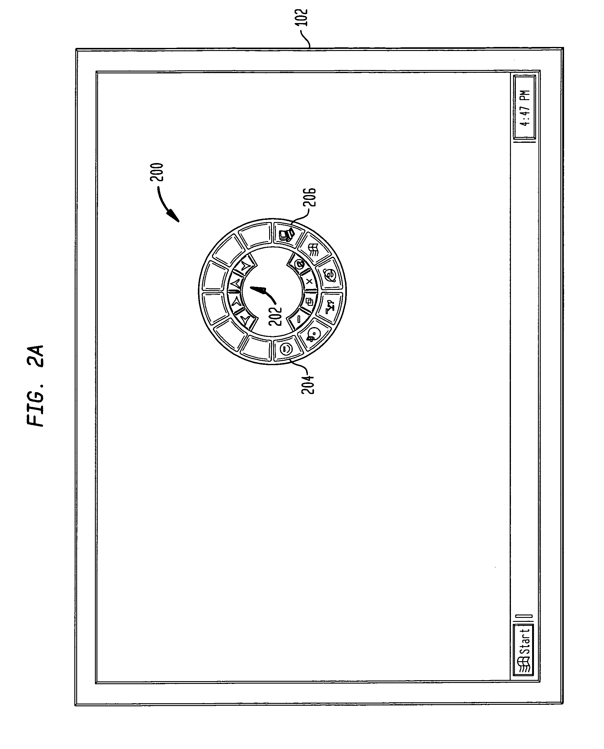
"The present invention is a user-defined interface (UDI) that reduces cursor commute in a cursor-based computing environment. The UDI has a plurality of buttons and a relative position that the user can customize. The user can also assign icons and commands to the buttons. The UDI can be activated by clicking a hotkey, mouse button, or turning on the apparatus. The invention also includes a method for managing the UDI based on user preferences. The technical effects of the invention include reducing screen clutter, improving user experience, and enabling users to customize commands according to their preferences."

Problems solved by technology

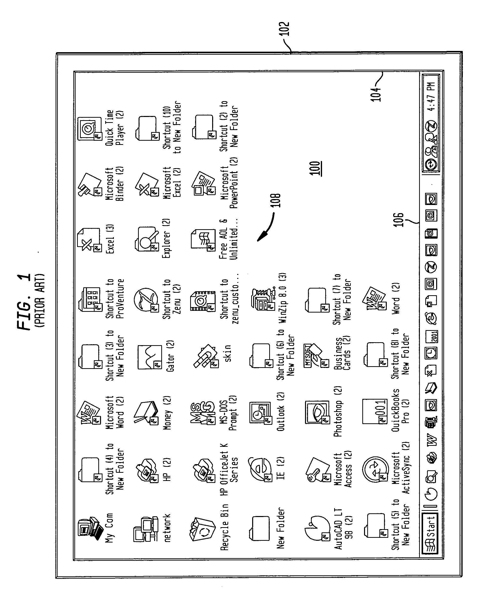
The manipulation of data in a data processing system is well known in the art and the large amounts of data that are available to the user of a modern state-of-the-art data processing system often become overwhelming in magnitude and complexity.
As a result of this increasing complexity, simplified interface methods and systems are needed between the user and the data processing system or device.
This movement is called “cursor commute.” This results in a time-consuming, less efficient and confusing user interface.
Therefore, it is difficult for the young, the elderly, handicapped, or any novice user to traverse and coordinate the position of the pointing device and, thus, the cursor with which the execution is made.
Pop-up menus, however, are limited to the number of commands they can contain and they often cover up part of the work area.

Method used


Image

  • User definable interface system and method
  • User definable interface system and method
  • User definable interface system and method

Examples


Embodiment Construction

[0049] The preferred embodiment of the present invention will now be discussed in detail. While specific features, configurations and arrangements are discussed, it should be understood that this is done for illustration purposes only. A person skilled in the relevant art will recognize that other steps, configurations and arrangements may be used without departing from the spirit and scope of the invention. Indeed, for the sake of brevity, conventional electronics, software and / or computer architecture, and other functional aspects of the method / apparatus (and components of the individual operating components of the apparatus) may not be described in detail herein. Furthermore, for purposes of brevity, the invention is frequently described herein as pertaining to data processing devices, such as personal computer or laptop computers, or set-top boxes in a television computing environment. It should be appreciated, however, that many other devices having a user viewable display for ...


PUM


Abstract

In a cursor-based computing environment having a display, a user definable interface (UDI) is displayed upon activation by a user. The UDI has a plurality of levels each having a plurality of buttons and is displayed in a selectable position about a pointer position in a display area to reduce pointer commute. The user selects a visual appearance and shape of the UDI, and the number of buttons. The user assigns a command to each of the plurality of buttons at each of the plurality of levels by dragging and dropping from one or more applications of the apparatus.

Description

CROSS-REFERENCE TO RELATED APPLICATIONS [0001] This application is a continuation of U.S. Ser. No. 09 / 986,765, filed Nov. 9, 2001 (now allowed), which application claims priority under 35 U.S.C. § 119(e) to U.S. Provisional Patent Application No. 60 / 247,643, filed Nov. 9, 2000, and 60 / 325,179, filed Sep. 28, 2001, which are all incorporated herein by reference in their entireties.COPYRIGHT AND TRADEMARK NOTICES [0002] A portion of the disclosure of this patent document contains material which is subject to copyright protection. The copyright owner has no objection to the facsimile reproduction by anyone of the patent document or the patent disclosure, as it appears in the Patent and Trademark Office patent files or records, but otherwise reserves all copyright rights whatsoever. [0003] Zenu is a trademark of Change Tools Inc. Unix is a registered trademark of The Open Group. Microsoft, Microsoft Windows, Window NT and / or other Microsoft products referenced herein are either trademar...

Claims


Application Information

Patent Timeline
Patent Type & Authority Applications(United States)
IPC IPC(8): G06F3/033G06F3/048G06F9/44
CPCG06F3/04817G06F9/4443G06F3/0482G06F9/451
Inventor LEAVITT, JOSEPH M.MILLS, SCOTT A.
Owner CHANGE TOOLS
Learn More