Multiple position air mattress system

a multi-position, air mattress technology, applied in the field of air mattresses, can solve the problem that conventional air mattresses cannot be positioned in more than one position

Inactive Publication Date: 2005-12-22
KASATSHKO VICTOR M
View PDF72 Cites 25 Cited by
  • Summary
  • Abstract
  • Description
  • Claims
  • Application Information

AI Technical Summary

Benefits of technology

[0011] An additional object is to provide a multiple position air mattress system that is efficient and easy to utilize.
[0012] A further object is to provide a multiple position air mattress system that may be stored in a compact storage position.
[0014] In an alternative embodiment, the air mattress system may include a fourth inflatable member that is positioned on the top side of the second inflatable member in the area near the hinge and supports the lumbar section of the user's body. The first inflatable member may be partitioned into multiple sections that are spaced apart along its length and pivotally joined together by one or more hinges. At least one of these sections is positioned under the user's legs. A fifth inflatable member is positioned under this at least one section to provide for adjustable elevation of the legs. A sixth inflatable member may be positioned on the top side of the second inflatable member in an area that supports the user's neck. The fourth inflatable member, fifth inflatable member, and / or the sixth inflatable member are independently inflatable. The pump unit is adapted to include an additional port(s) and hose(s) that are coupled to the respective fourth, fifth and / or sixth inflatable members to provide for independent inflation thereof. The fourth inflatable member (which provides lumbar support) may be inflated to different pressure / comfort levels independently of the pressure / comfort levels of the first and second inflatable members. The fifth inflatable members may be inclined to different inflation levels, independent of the pressure levels of the first and second inflatable members, to control the elevation of the user's legs. Such elevation control provides relief for swelling of the legs as well as for circulatory ailments of the legs (e.g., varicose veins). The sixth inflatable member (which provides neck support) may be inflated to different pressure / comfort levels independently of the pressure / comfort levels of the first and second inflatable members.
[0015] Preferably, a cover substantially (or fully) encloses the tops, bottoms and sides of the inflatable members of the air mattress system. The top, bottom and sides of the cover are preferably quilted. The top of the cover (i.e., the portion that overlies the top surfaces of the first, second and possibly the fourth and / or sixth inflatable members and that contacts the user's body) is preferably thick and plush to provide added comfort, and may incorporate fillings such as down feathers, latex foam, memory foam, cellulose, etc. The bottom of the cover is preferably realized from a thin quilted material, which encloses the bottom of the first, third and possibly fifth inflatable members completely.
[0016] Foam members may surround at least three sides of the perimeter of the first inflatable member and / or the second inflatable member. The height of the foam members lies below the full height of the respective member, thus providing air support over 100 percent of the top surface of the air mattresses system. The foam members also aid against the user “bottoming out” when sitting on the edge of the air mattress system.

Problems solved by technology

Conventional air mattresses are not capable of being positioned in more than a prone bed position.

Method used


Image

  • Multiple position air mattress system
  • Multiple position air mattress system
  • Multiple position air mattress system

Examples


first alternative embodiment

J. First Alternative Embodiment

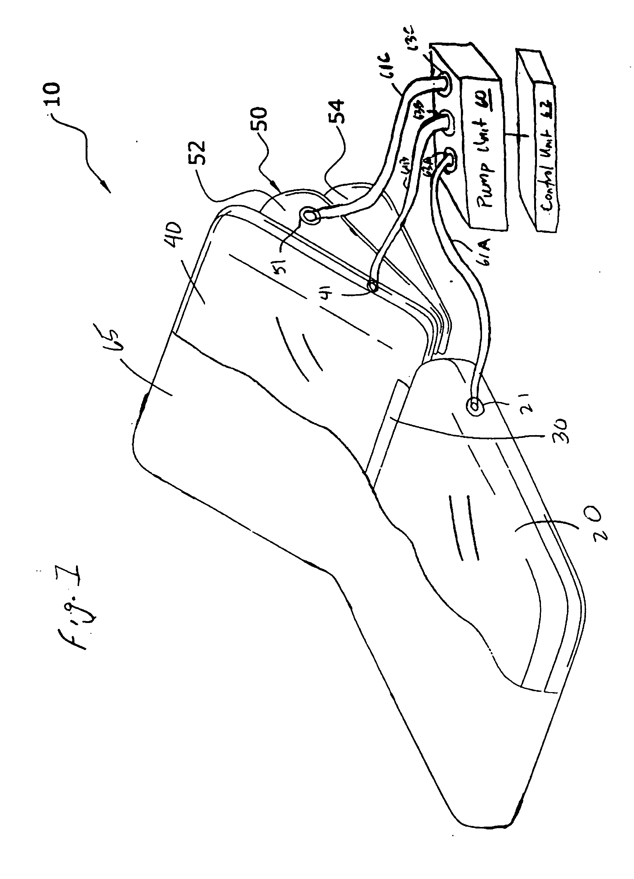
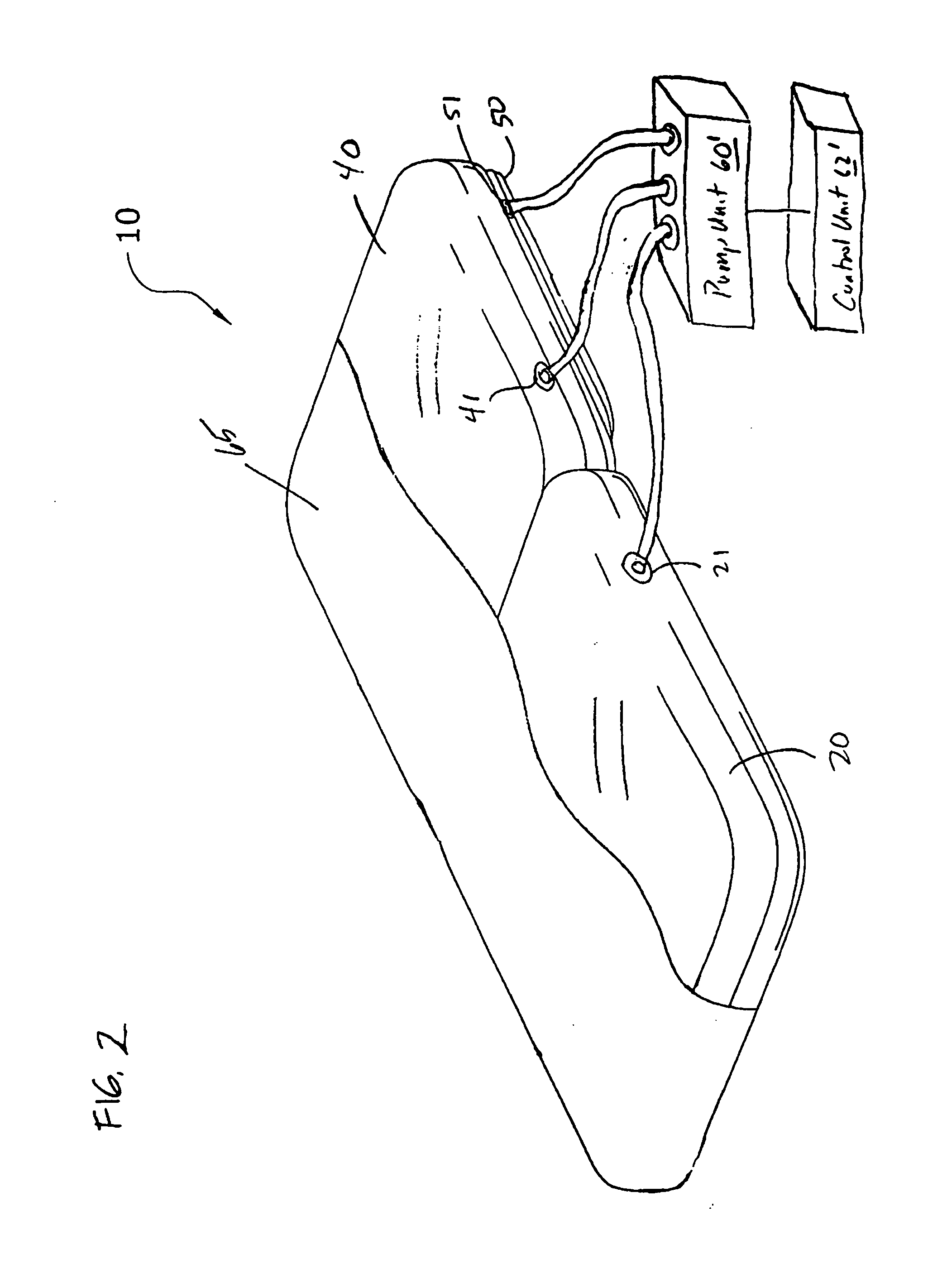
[0046] In an alternative embodiment as shown in FIGS. 4, 5A and 5B, the air mattress system 10′ includes the first inflatable mattress 20, the second inflatable mattress 40, the bellows unit 50, and hinge 30 as described above. A fourth inflatable unit 35 is affixed to the top side of the second mattress 40 in the area near the hinge 30 and extends transverse to the lengthwise dimension of the mattress system. The fourth inflatable unit 35 supports the lumbar section of the user's body in both the prone bed position and the inclined position. The fourth unit 35 is preferably comprised of reinforced PVC, reinforced rubber or other suitable material(s) capable of retaining pressurized air within. In addition, the fourth unit 35 may have internal webs or beams that couple the top and bottom surfaces of the unit 35. Alternatively, other support structure(s), such as a series of cylindrical or otherwise shaped columns that couple the top and bottom surfaces...

second alternative embodiment

K. Second Alternative Embodiment

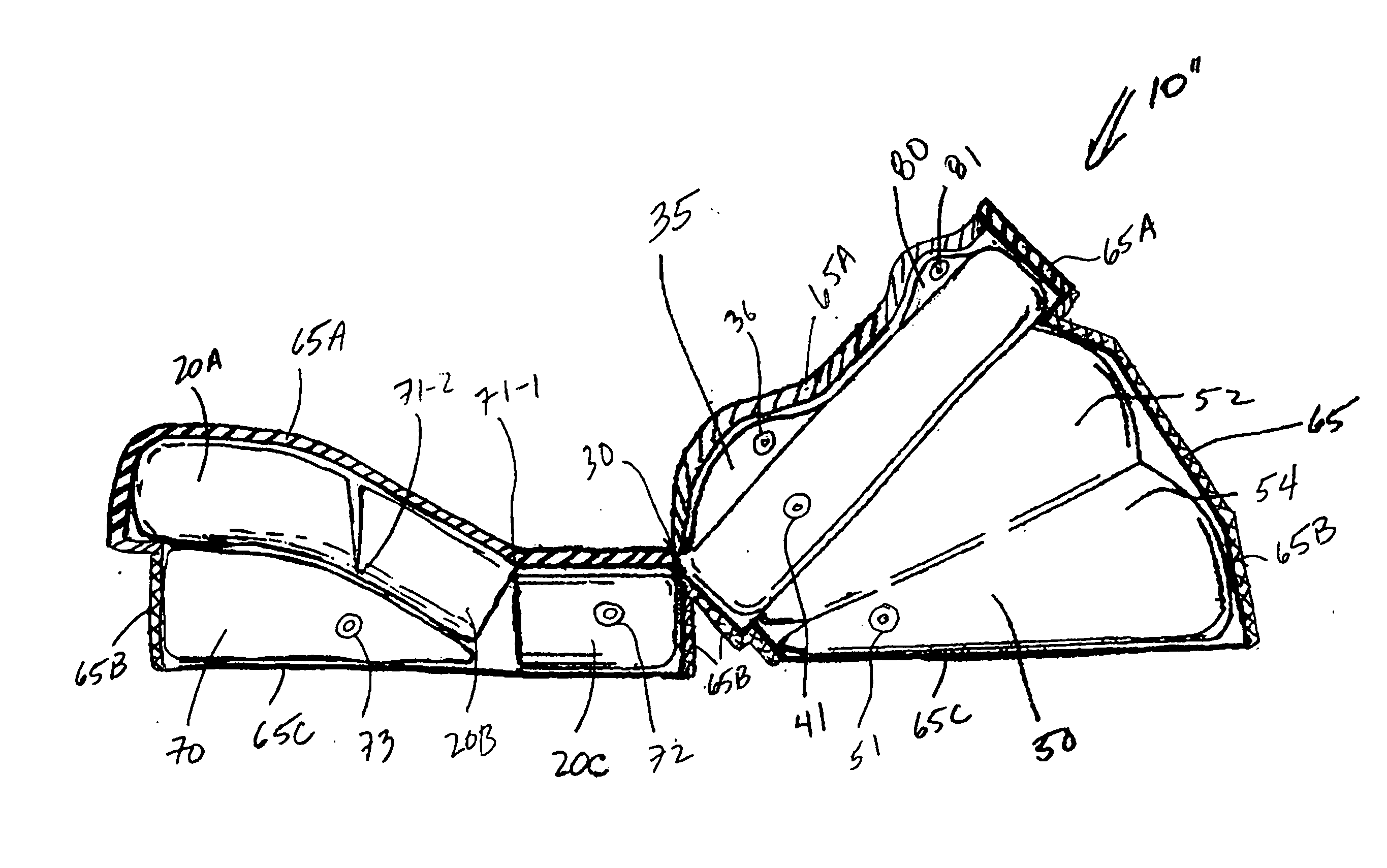
[0049] In yet another embodiment as shown in FIG. 6, the air mattress system 10″ includes the second inflatable mattress 40, the bellows unit 50, and the fourth unit 35 as described above. The first mattress 20 is modified to include three sections: a front section 20A, a middle section 20B and back section 20C. The back section 20C is connected to the second mattress 40 via hinge 30. The middle section 20B is connected to the back section 20C by a second hinge 71-1. The front section 20C is connected to the middle section 20B by a third hinge 71-2. The three sections 20A, 20B, 20C are preferably fluidly interconnected to one another by non-valved flow paths (for example, flow paths that are part of the hinges 71-1 and 71-2) to allow for simultaneous or conditioned pressurization of the three sections 20A, 20B and 20C via fluid coupling means 72 from the pressurized air source. Alternatively, if desired, the three sections 20A, 20B, 20C can be inflate...


PUM


Abstract

A multiple position air mattress system for achieving various support positions includes a first mattress, a second mattress, and a bellows unit attached to the second mattress. The bellows unit is extendable for either elevating the second mattress or providing a support for an individual. The multiple position air mattress system can assume a prone bed position with the mattresses longitudinally adjacent each other and the bellows unit deflated and an inclined bed position with the mattresses longitudinally adjacent each other and the bellows unit inflated under the second mattress. In the inclined bed position, the degree of elevation of the second mattress can be finely adjusted by increasing or decreasing the inflation level of the bellows unit. A fourth inflatable member may be positioned on the top side of the second mattress to support the lumbar section of the user's body. A fifth inflatable member may be positioned under the user's leg to provide adjustable elevation of the legs. A sixth inflatable member may be positioned on the top side of the second mattress to support the user's neck. A pump unit including a plurality of ports and a corresponding plurality of hoses are coupled to inflatable members to provide for independent inflation thereof. A control unit is operably coupled to the pump unit to provide for independent control of the inflation levels of the members. Preferably, a cover substantially encloses the tops, bottoms and sides of the members. Foam inserts may surround at least three sides of the perimeter of the first and / or second mattresses.

Description

CROSS REFERENCE TO RELATED APPLICATIONS [0001] The present application is a continuation-in-part of U.S. patent application Ser. No. 11 / 079,939, which is a continuation-in-part of U.S. patent application Ser. No. 10 / 744,874, filed Dec. 23, 2003, which is a continuation-in-part of U.S. patent application Ser. No. 10 / 350,587, filed Jan. 24, 2003, all of which are herein incorporated by reference in their entireties.BACKGROUND OF THE INVENTION [0002] 1. Field of the Invention [0003] The present invention relates generally to air mattresses and more specifically it relates to a multiple position air mattress system for achieving various support positions. [0004] 2. Description of the Related Art [0005] Air mattresses have been in use for years. A conventional air mattress is comprised of a rectangular flat structure that is inflatable forming a bed-like structure. Conventional air mattresses may have pumps built into them or may be inflated from an external air source. Conventional air ...

Claims


Application Information

Patent Timeline
Patent Type & Authority Applications(United States)
IPC IPC(8): A47C4/54A47C20/04A47C27/08A47C27/10
CPCA47C4/54A47C27/10A47C27/082A47C20/048
Inventor KASATSHKO, VICTOR M.
Owner KASATSHKO VICTOR M
Why Eureka
Try Eureka