Cylinder head gasket with one-way coolant flow valve

a coolant flow valve and cylinder head technology, which is applied in the direction of cylinders, mechanical equipment, machines/engines, etc., can solve the problems of engine components damage, inadvertently establishing an abnormal direction of coolant flow, etc., and achieve the effect of preventing abnormal coolant flow

Inactive Publication Date: 2005-12-22
FEDERAL MOGUL WORLD WIDE LLC
View PDF5 Cites 18 Cited by
  • Summary
  • Abstract
  • Description
  • Claims
  • Application Information

AI Technical Summary

Benefits of technology

[0007] The subject invention overcomes the undesirable occurrence of reverse coolant flow by providing a one-way valve directly on the gasket body which functions to allow coolant flow in the normal direction but to prevent coolant flow in an abnormal direction.
[0009] According to yet another aspect of the invention, a method for preventing abnormal coolant flow in an internal combustion engine is provided. The method comprises the steps of providing an engine having a circuitous coolant flow path passing through a cylinder head and a block, circulating liquid coolant through the flow path in a normal direction, compressing a head gasket between the cylinder head and the block to contain combustion gases, forming a coolant flow opening in the head gasket aligned with the flow path to permit the movement of liquid coolant therethrough in the normal direction, and automatically blocking the flow opening with a one-way valve carried on the head gasket to prevent coolant flow through the engine in an abnormal direction.

Problems solved by technology

Depending upon the combination of flow control vales actuated, it is possible to inadvertently establish an abnormal direction of coolant flow through the cooling system.
Reverse coolant flow is undesirable, and in some situations can result in damage to the engine components.

Method used


Image

  • Cylinder head gasket with one-way coolant flow valve
  • Cylinder head gasket with one-way coolant flow valve
  • Cylinder head gasket with one-way coolant flow valve

Examples


Embodiment Construction

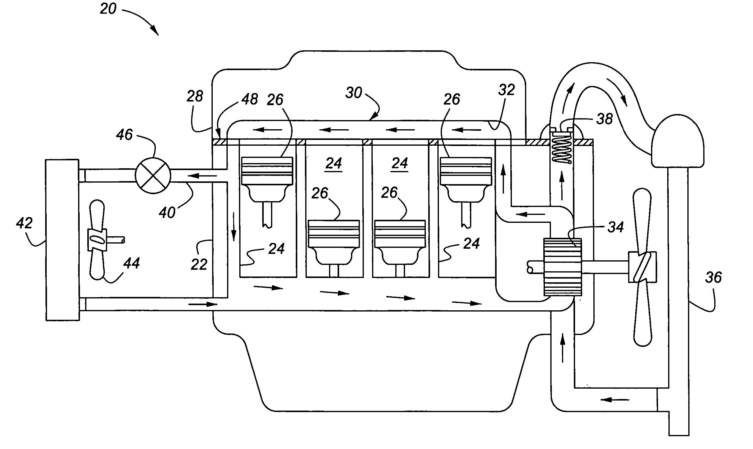
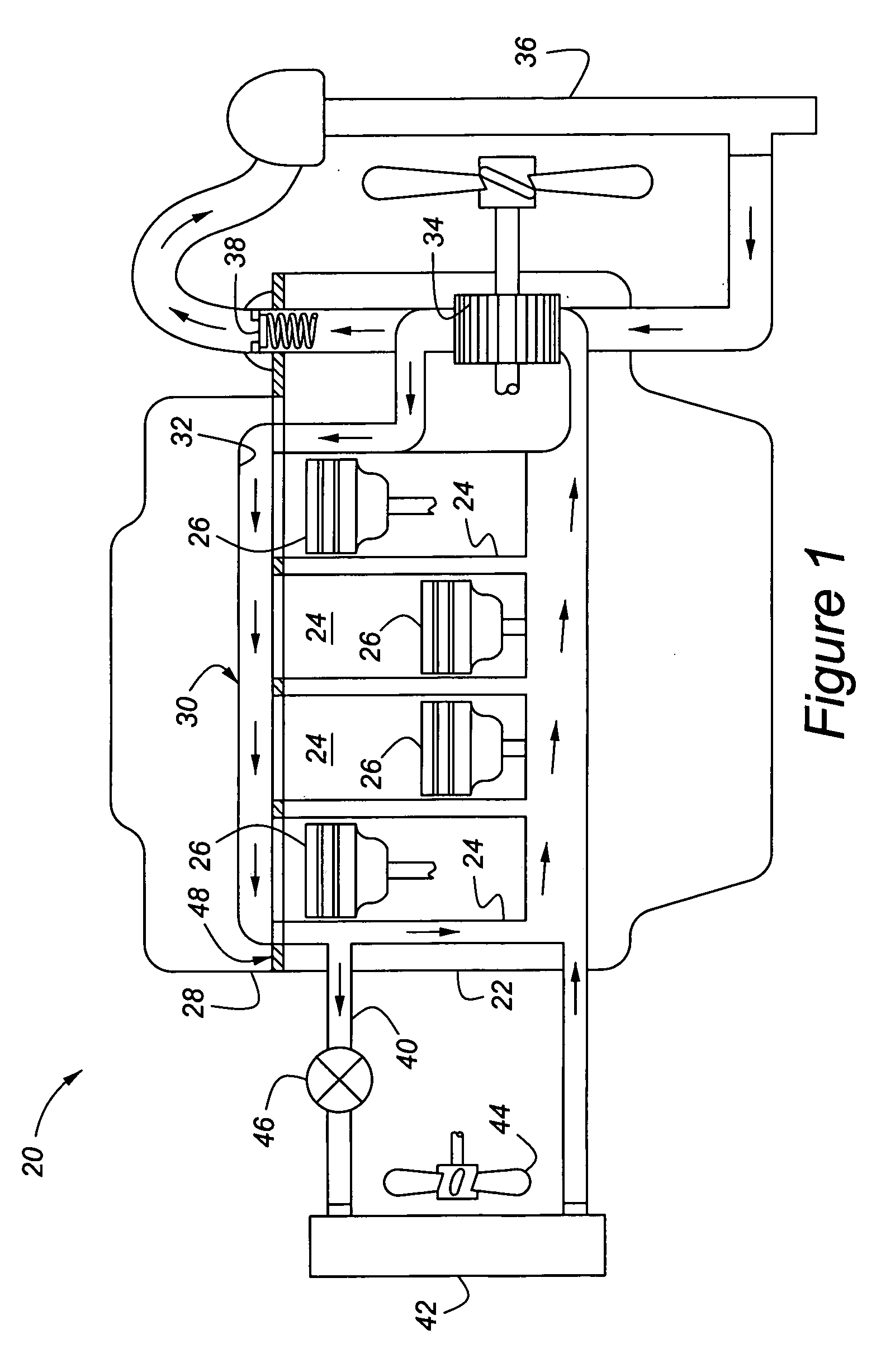
[0021] Referring to the figures, wherein like numerals indicated like or corresponding parts throughout the several views, a simplified schematic of a liquid cooled internal combustion engine is generally shown a 20 in FIG. 1. The engine 20 includes a block 22 having a plurality of combustions chambers 24 formed therein. A piston 26 reciprocates in each combustion chamber 24 through two or four strokes to produce power through a combustion process which generates considerable heat as a byproduct. A cylinder head 28 is fixed to the block 22 and covers each of the combustion chambers 24 to seal in combustion gases.

[0022] To manage the considerable heat generated through the combustion process, a cooling system, generally indicated at 30, is provided with portions integrated into the block 22 and the cylinder head 28. The cooling system 30 includes a circuitous flow path 32 through which liquid coolant is routed from the cylinder head 28 to the cylinder block 22 under the influence of...


PUM


Abstract

A head gasket (48) which acts, when clamped between a cylinder head (28) and a block (22) in a liquid cooled internal combustion engine (20), to form a seal around the combustion chambers (24). A coolant flow path (32) routes through the engine (20) and its directed, in part, through the cylinder head (28) and the block (22), with a corresponding flow opening (54) formed in the head gasket (48) to accommodate flow of liquid coolant in a normal direction. The head gasket (48) includes a one-way valve (58) positioned in the flow opening (54) to allow the flow of coolant in a normal direction but to prevent the flow of liquid coolant through the flow opening (54) in an abnormal, reverse direction. The one-way valve (58) includes movable gate (66) which may be biased against a valve seat (64) in a normally closed condition. The one-way valve (58) can be made as a loose piece article of manufacture which is held in flow opening (54) by self-locking retention clips.

Description

CROSS-REFERENCES TO RELATED APPLICATIONS [0001] This patent application claims priority to U.S. Provisional Patent Application Ser. No. 60 / 581898, filed Jun. 22, 2004.FIELD OF THE INVENTION [0002] The invention relates to a method and assembly for preventing abnormal coolant flow in an internal combustion engine, and more particularly toward an improved head gasket having an integrated one-way flow control valve. DESCRIPTION OF THE RELATED ART [0003] Head gaskets act, when clamped between the cylinder head and the block of an internal combustion engine, to form seals around the cylinder bores. Head gaskets also provide openings for coolant flow paths and lubrication passages between the cylinder head and the block. The prior art includes various configurations of head gaskets which incorporate either mechanically or thermostatically operated valves mounted on the gasket body to control the flow of liquid between the cylinder head and the block. Such prior art gaskets are also know t...

Claims


Application Information

Patent Timeline
Patent Type & Authority Applications(United States)
IPC IPC(8): F01P7/14F02B75/18F02F1/36F02F11/00F16J15/06F16J15/08
CPCF01P7/14F02F11/002F16J2015/0856F16J15/0818F16J15/064
Inventor VIALARD, DANIEL J.TRIPATHY, BHAWANI
Owner FEDERAL MOGUL WORLD WIDE LLC
Why Eureka
Try Eureka