Full cutoff area light fixture

a full-cutoff, light fixture technology, applied in outdoor lighting, lighting and heating equipment, instruments, etc., can solve the problems of reducing the efficiency of the luminaire, and the efficiency of the sag lens, so as to achieve efficient distribution of light over a large area

Inactive Publication Date: 2005-12-22
PHILIPS LIGHTING NORTH AMERICA CORPORATION
View PDF18 Cites 32 Cited by
  • Summary
  • Abstract
  • Description
  • Claims
  • Application Information

AI Technical Summary

Benefits of technology

[0006] One object of the present invention is to create a full cut

Problems solved by technology

Flat lenses have been found not to be very efficient in allowing the light to pass through since much of the incident light is not normal to the lens and is therefore reflected back into the luminaire.
This greatly reduces the efficiency of the luminaire.
However, the sag lens does not provide for a full cutoff luminaire.
In some jurisdictions the sag lens luminaires are forbidden because of light pollution issues.
Sag lenses are also less efficient since light is projected above 90° nadir rather than on a predefined area below.
Additionally,

Method used


Image

  • Full cutoff area light fixture
  • Full cutoff area light fixture
  • Full cutoff area light fixture

Examples


Embodiment Construction

[0032] The invention, both as to organization and method of operation, may best be understood by reference to the following description taken in conjunction with the accompanying drawings of which:

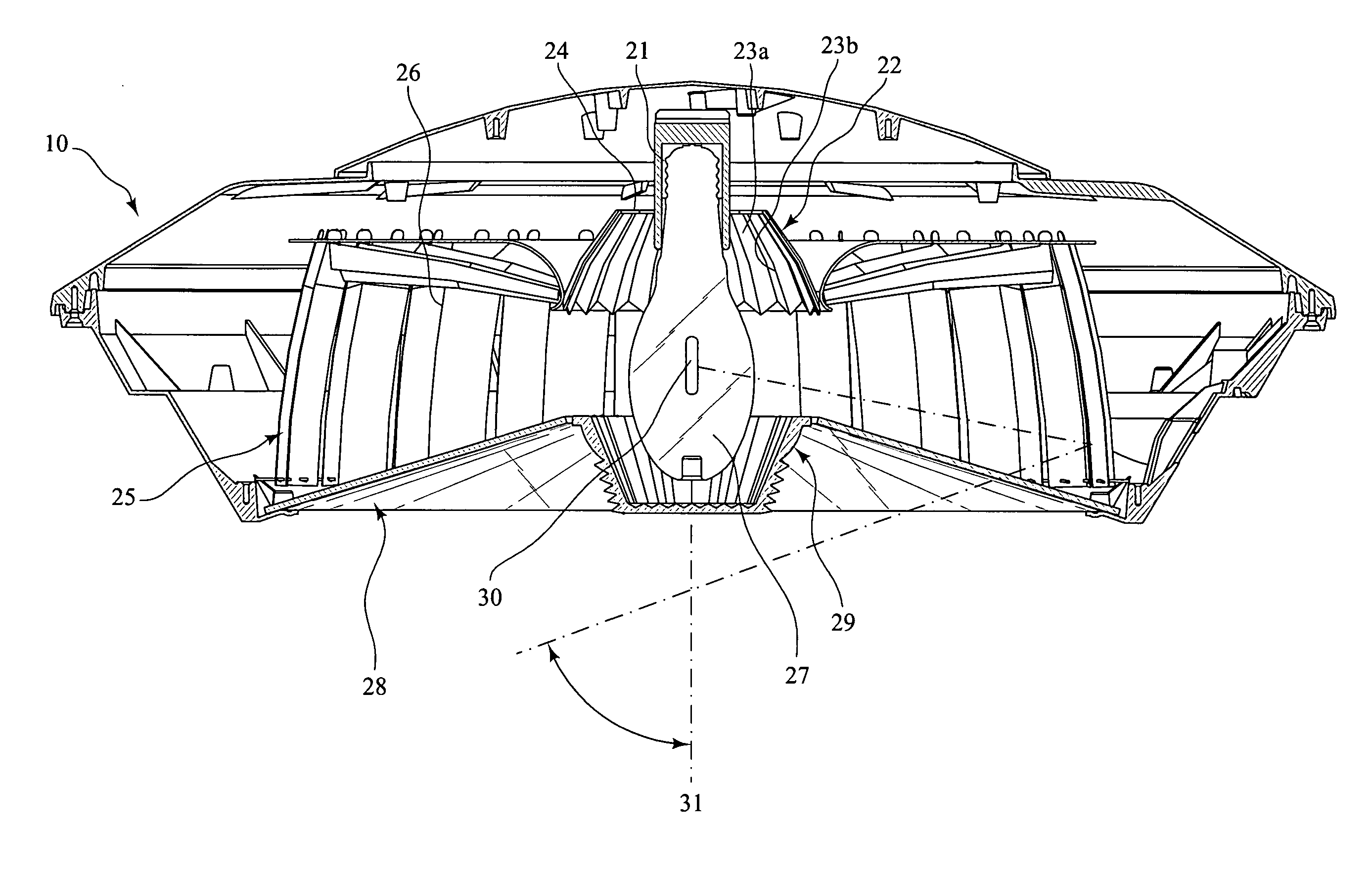
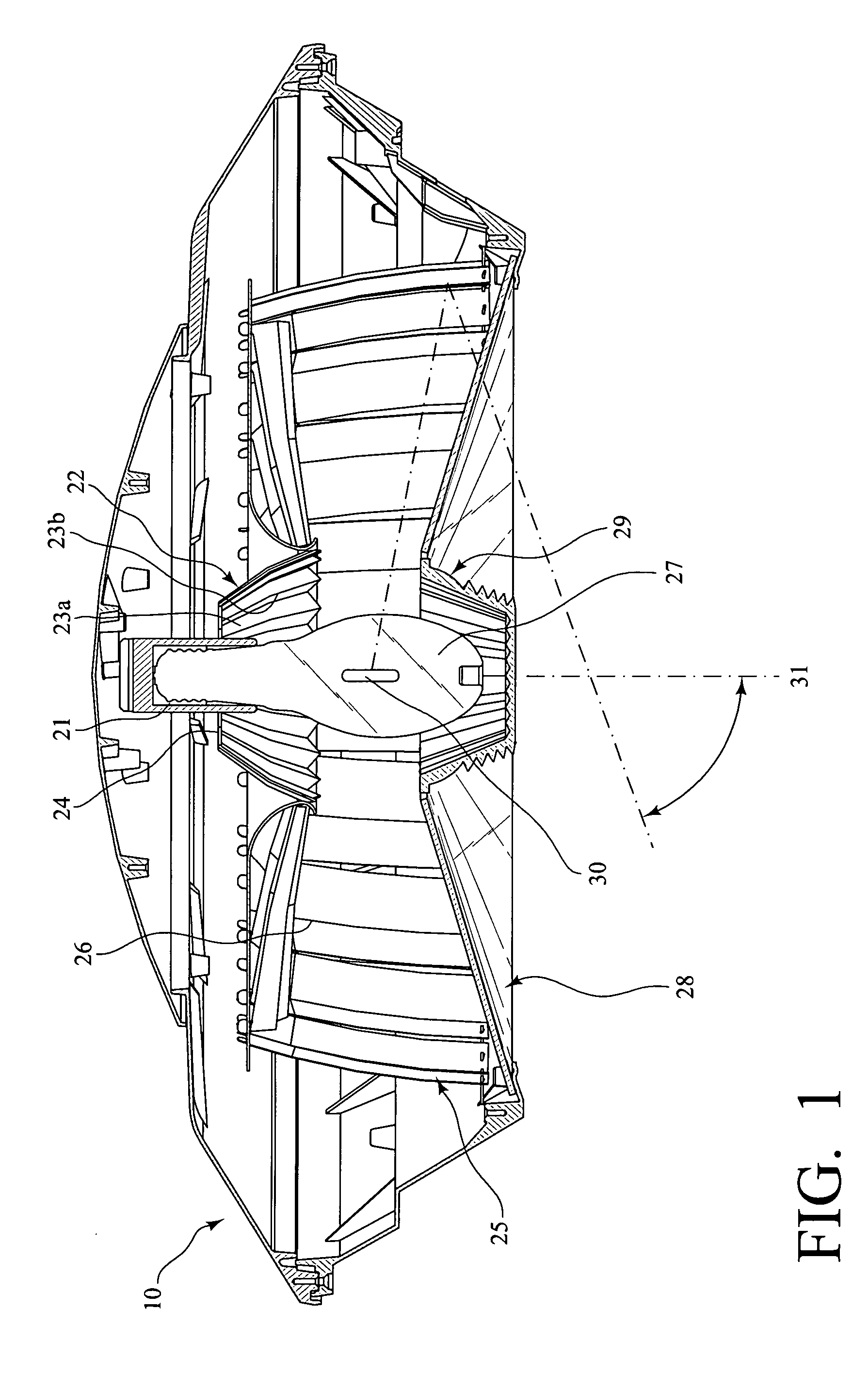
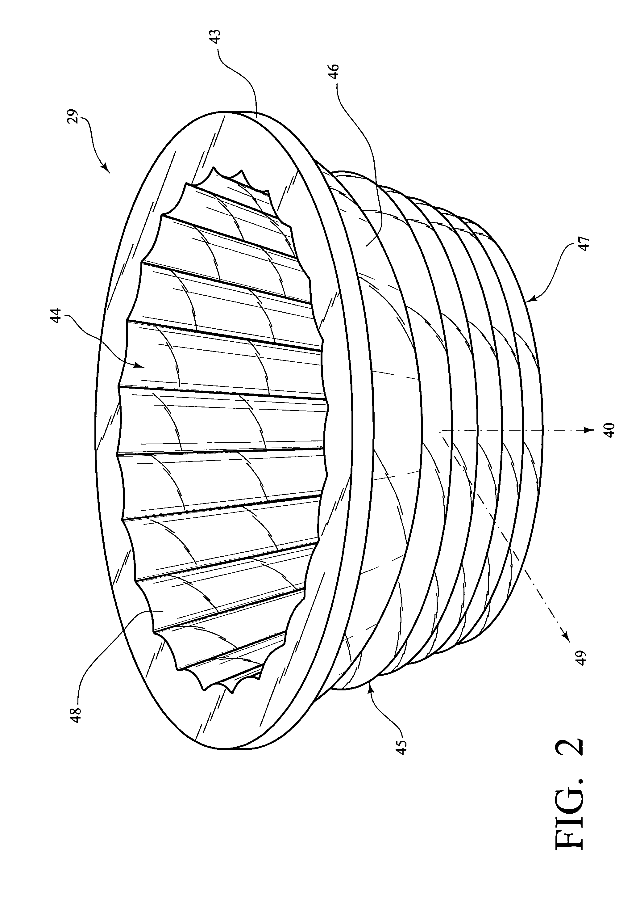
[0033]FIG. 1 is a cross-sectional view of an embodiment of the full cutoff luminaire of the present invention. The luminaire is designed to project 360° of radial illumination towards and evenly onto an architectural surface below. This embodiment of the luminaire is shown to be comprised of four optical elements contained within and above the lower edge of an open bottomed housing 10: an upper reflector 22; a radial reflector 25; an inverted conical lens 28; and an optical lens 29.

[0034] Upper reflector 22 is designed to reflect a vertical segment of light radiation from lamp 27 or arc tube source 30 where HID lamp 27 is vertically installed in lamp holder 21. Lamp holder 21 is centrally mounted in housing 10 above a lamp region within housing 10. The upper reflector 22 projects a porti...


PUM


Abstract

A full cutoff luminaire having a housing with an open bottom, a vertically mounted lamp centrally located within the housing, a radial reflector surrounding a portion of the lamp and a downwardly extending optic lens having an open top enshrouding a lower portion of the lamp wherein light emitted from the luminaire does not exceed 90° above nadir.

Description

CROSS-REFERENCE TO RELATED APPLICATIONS [0001] This application claims priority to and benefit from U.S. application Ser. No. 60 / 538,620, filed Jan. 23, 2004, which is incorporated herein by reference.TECHNICAL FIELD OF THE INVENTION [0002] The present invention relates generally to the lighting field, and, more particularly, to full cutoff radial luminaires having a high intensity discharge lamp for lighting a large area. DESCRIPTION OF THE PRIOR ART [0003] In the past, large surface areas (i.e. parking lots) have been illuminated with luminaires having a high intensity discharge lamp, reflector(s), and a flat or sag lens covering the bottom of the luminaire. Flat lenses have been found not to be very efficient in allowing the light to pass through since much of the incident light is not normal to the lens and is therefore reflected back into the luminaire. For instance, it has been determined that approximately up to 20% of 70° incident light reflects back into the luminaire. This...

Claims


Application Information

Patent Timeline
IPC IPC(8): F21V5/02F21V5/04F21V7/00F21V7/09F21V13/04
CPCF21V5/02F21V5/045F21V7/0025G02B3/08F21V13/04F21W2131/103F21V7/09F21V5/10
Inventor SUMMERFORD, ROBERTBAROZZINI, CLAUDESIMON, JERRY
Owner PHILIPS LIGHTING NORTH AMERICA CORPORATION
Why Eureka
Try Eureka