
Vent pipe support system and method of installation

Inactive Publication Date: 2005-12-29
LAWVER DONALD D JR
View PDF7 Cites 27 Cited by
  • Summary
  • Abstract
  • Description
  • Claims
  • Application Information

AI Technical Summary

Benefits of technology

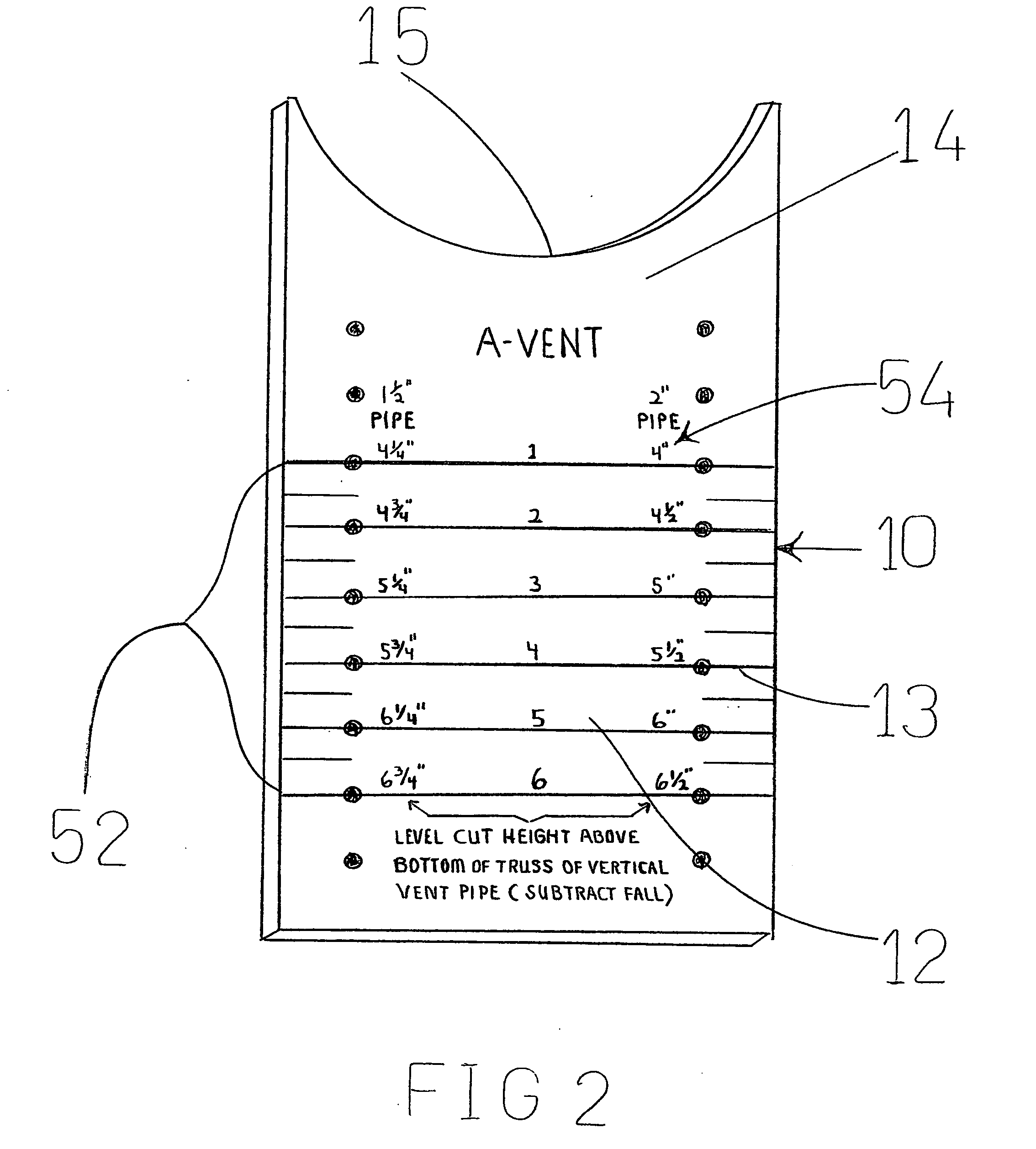
[0006] The present invention provides a vent-pipe installation and support system for installing and supporting a vent-pipe system above a joist. This system comprises perpendicular vent-pipe supports for supporting vent-pipes which run generally perpendicular to the joists, and parallel-vent-pipe supports, for supporting vent-pipes which run generally parallel to the joists. The perpendicular-vent-pipe supports comprise a body portion, which is mounted to a joist, and a top portion having a generally C-shaped cut-out. The C-shaped cut-out opens away from the joist, and is sized to fit the vent-pipe, The body portion has graduated markings parallel to the joist top surface, wherein when consecutive graduated markings align with the joist top surface on every other consecutive joists, a supporte

Problems solved by technology

Further, modifying these hooks to support the pipes requires tightly locking on to the pipe, which does not allow for expansion and contraction of the pipe.
Further, this hanger requires that the hanger be installed on the pipe before the pipe is installed, which makes installation complicated.
A further issue is when vent pipes run the same direction as the joists.

Method used


Image

  • Vent pipe support system and method of installation
  • Vent pipe support system and method of installation
  • Vent pipe support system and method of installation

Examples


Embodiment Construction

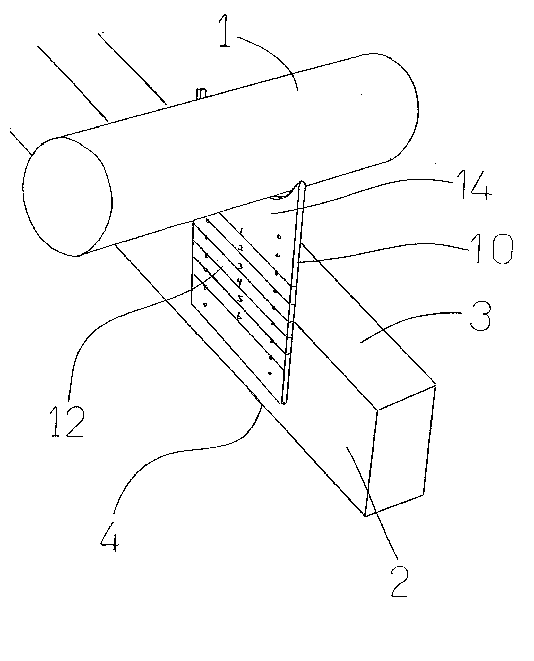
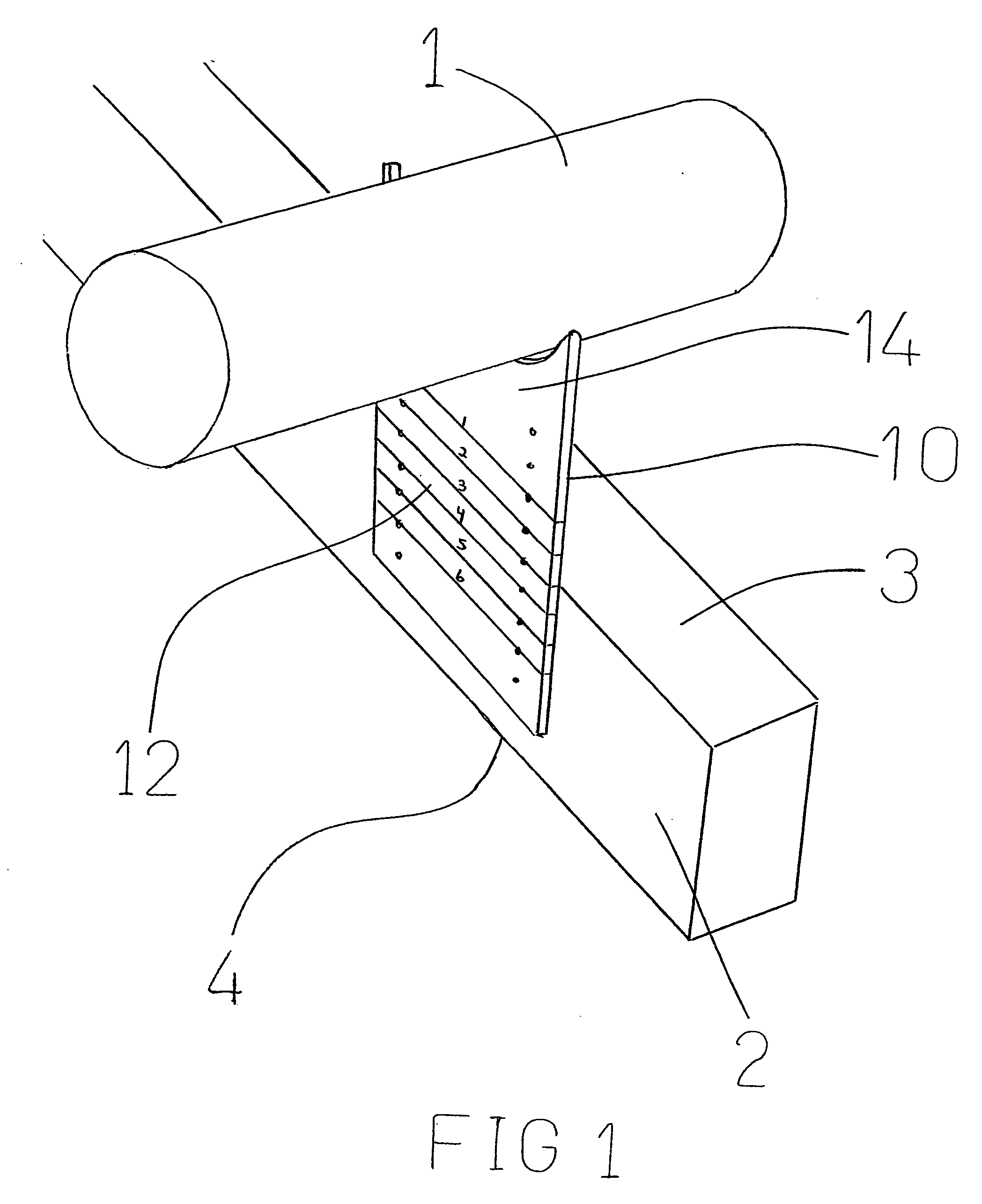
[0021] Various aspects of the invention are presented in FIGS. 1-14 which are not drawn to scale and in which like components are numbered alike. Referring now to FIGS. 1-14, according to an aspect of the invention, a vent-pipe support 10 for supporting a vent-pipe 1 above a joist 2, wherein the joists 2 have a top surface 3, and a bottom surface 4, comprises a body portion 12, and a top portion 14. The body portion 12 is mounted to the joist 2. The top portion 14 has a generally C-shaped cut-out 15 which opens away from the joist 2, and which is sized to fit the vent-pipe 1. The cut-out 15 can be sized such that a variety of pipe sizes would fit. The most common application would have a cut-out 15 which could be used for either a 2 inch pipe or a 1½ inch pipe, two standard vent pipe sizes. Prior art designs require hanging the pipe, which requires clipping the pipe into a support, which requires a snug fit. In the present invention, supporting the pipe from underneath does not requ...


PUM


Abstract

The present invention provides a vent-pipe installation and support system for installing and supporting a vent-pipe system above a joist. This system comprises perpendicular vent-pipe supports for supporting vent-pipes which run generally perpendicular to the joists, and parallel-vent-pipe supports, for supporting vent-pipes which run generally parallel to the joists. The perpendicular-vent-pipe supports comprise a body portion, which is mounted to a joist, and a top portion having a generally C-shaped cut-out. The C-shaped cut-out opens away from the joist, and is sized to fit the vent-pipe, The body portion has graduated markings parallel to the joist top surface, wherein when consecutive graduated markings align with the joist top surface on every other consecutive joists, a supported vent pipe will be at a required grade. The parallel-vent-pipe supports comprise a post having a top, and having a mounting surface, whereby the post mounting surface is mounted to the joist, and a pipe engaging member extending away from the post mounting surface, wherein the pipe engaging member is at the top of the post, and wherein the pipe engaging member is a generally C-shaped cut-out. The C-shaped cut-out opens away from the joist, and is sized to fit the vent-pipe. The post has graduated markings parallel to the joist top surface, wherein when consecutive graduated markings align with the joist top surface on consecutive parallel-vent-pipe supports when the parallel-vent-pipe supports are spaced a predetermined distance apart, a supported parallel-vent-pipe will be at a required grade.

Description

BACKGROUND [0001] The present invention is in the field of ventilation systems. More specifically this invention relates to a system of installation and support for piping for a ventilation system. [0002] Plumbing in residential and commercial construction needs to be vented. This ventilation pipe needs to exit through the roof of the building, and be installed at a certain grade to allow for drainage. Current methods of installation include using straps, or J-Hooks (a trademark of J-Hook industries, Inc.) disclosed in U.S. Pat. No. 4,409,428 intended for suspending pipe, and modifying them in the field to support pipe. This entails adding extra wood bracing to hang or support these pipes. Often the ventilation pipe support system is created uniquely for the specific building as the ventilation pipes are being installed. Further, modifying these hooks to support the pipes requires tightly locking on to the pipe, which does not allow for expansion and contraction of the pipe. [0003] ...

Claims


Application Information

Patent Timeline
IPC IPC(8): E03C1/122F16L3/02F16L3/08F16L3/24F16L3/26
CPCF16L3/24F24F13/0254F16L3/26
Inventor LAWVER, DONALD D. JR.
Owner LAWVER DONALD D JR
Learn More