
System and method for generating disk failure warning using read back signal

a read-back signal and read-back signal technology, applied in the field of hard disk drives, can solve the problems of insufficient read-back signal amplitude by itself to predict and/or detect lube accumulation or contamination pickup, and achieve the effect of lowering the flying heigh

Inactive Publication Date: 2005-12-29
HITACHI GLOBAL STORAGE TECH NETHERLANDS BV
View PDF8 Cites 8 Cited by
  • Summary
  • Abstract
  • Description
  • Claims
  • Application Information

AI Technical Summary

Benefits of technology

[0005] Having made the following critical observation, the invention disclosed herein is provided. Specifically, the invention recognizes that impending failure from a head crash due to lowered flying height caused by lubricant pickup and/or cont...

Problems solved by technology

In any case, lube pick up and contamination accumulation between the disk and slider changes the dynamics of the HDI by changing the flying height of the slider above the disk, potentially leading to contact between the heads and disk and, hence, a potential HDD failure.
Hence, read-back signal amplitude by itself is insufficient to predict and / or detect lube accumulation or contamination pickup.

Method used


Image

  • System and method for generating disk failure warning using read back signal
  • System and method for generating disk failure warning using read back signal
  • System and method for generating disk failure warning using read back signal

Examples


Embodiment Construction

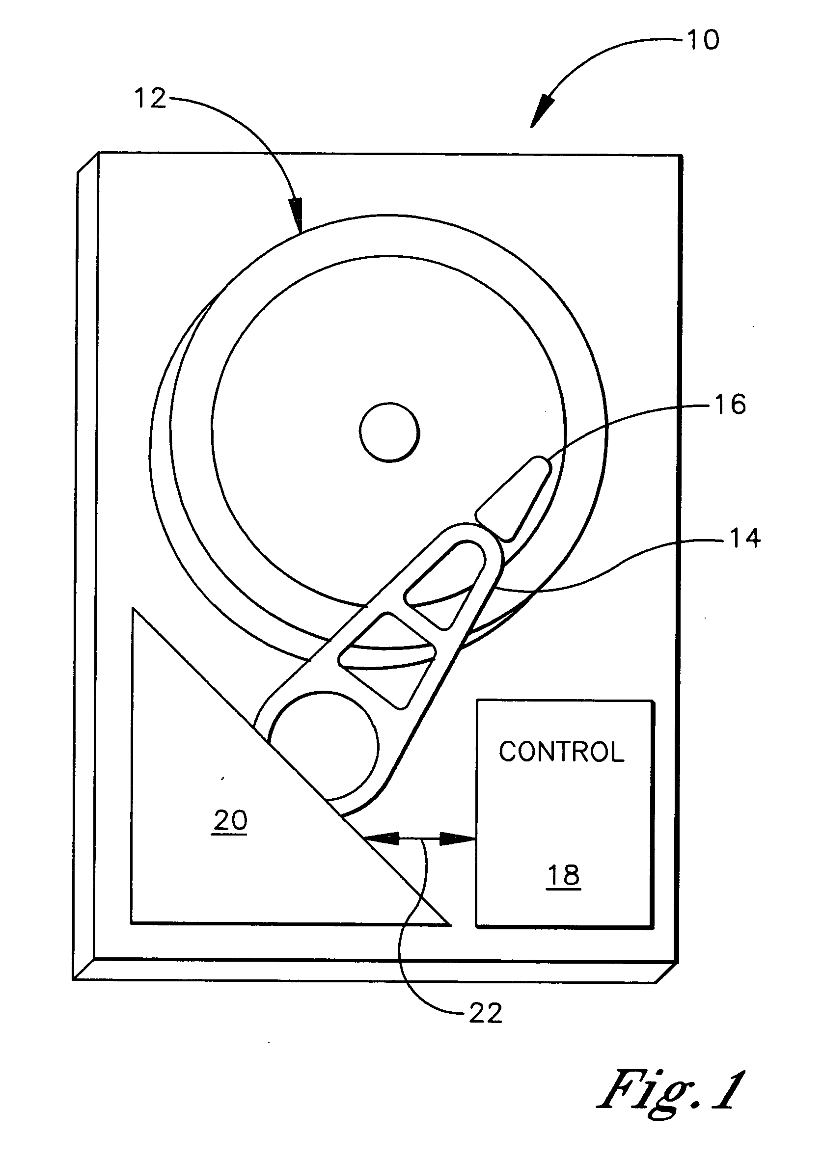
[0017] Referring initially to FIG. 1, a device is shown, generally designated 10, for storing data on a storage medium 12 that in one embodiment may be implemented by plural storage disks in a hard disk drive (HDD). When implemented as a hard disk drive, the device 10 includes an arm 14 having a read / write head 16 (part of what is colloquially referred to as a “slider”) on the end thereof in accordance with hard disk drive principles. The data storage region 12 may be managed by a controller 18 that can be a conventional hard disk drive controller modified per the logic below. The controller 18 controls an electro-mechanical actuator 20 by sending signals over a path 22 in accordance with principles known in the art to read data from and to write data to the disks 12.

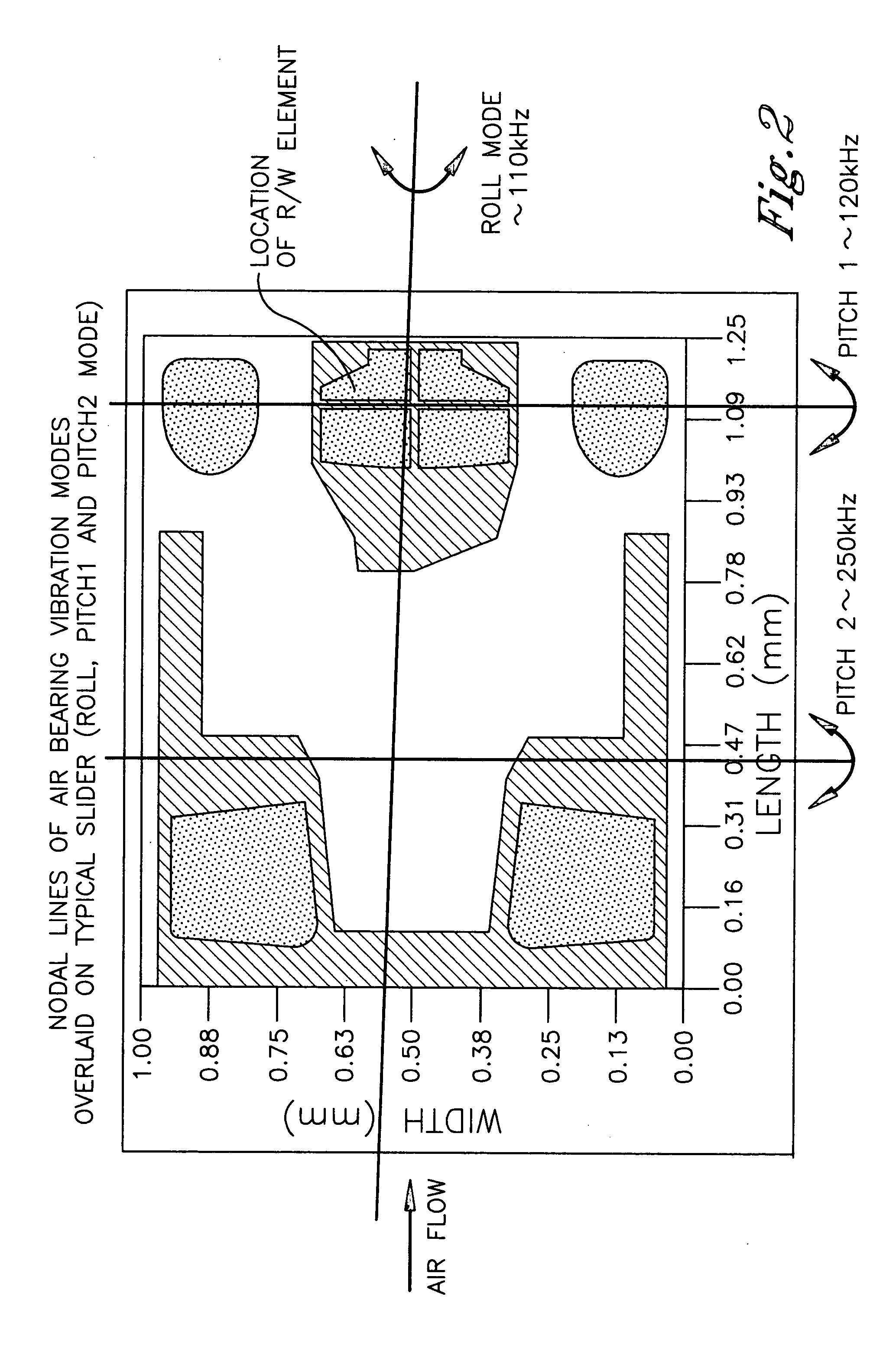
[0018] Referring briefly to FIG. 2, the “pitch” of the head 16 refers to its up-and-down motion toward and away from the disk; thus, the pitch frequency is the frequency of the vertical bouncing oscillations of the hea...


PUM


Abstract

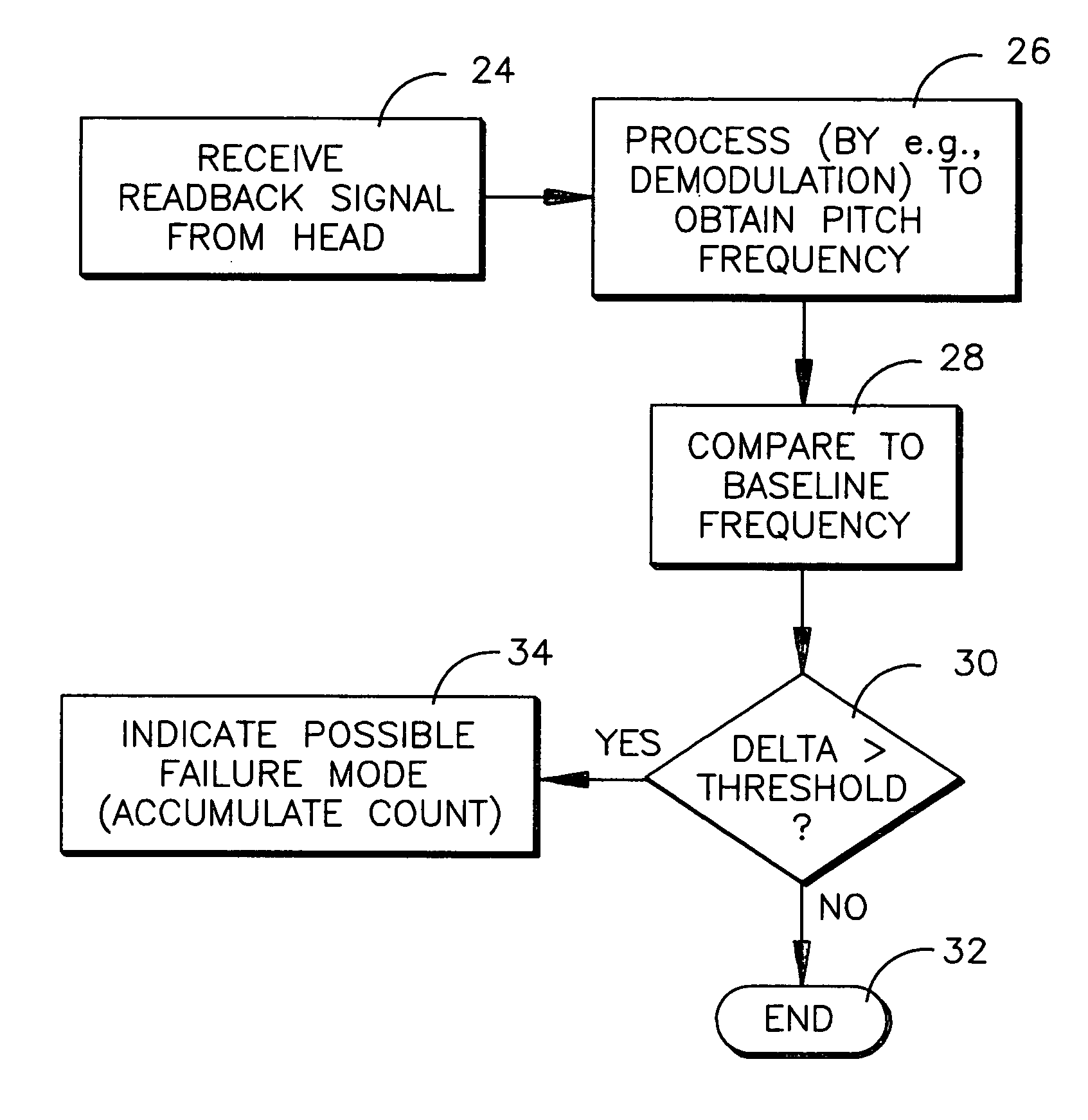
The read-back signal from a HDD head is demodulated to find the pitch frequency of the head, which can be compared to a baseline value to determine if it has increased, indicating a possible failure due to contamination or lubricants pick up. Or, the pitch frequency can be used during manufacturing of a burnished pad head to determine when burnishing has been completed.

Description

FIELD OF THE INVENTION [0001] The present invention relates generally to hard disk drives. BACKGROUND OF THE INVENTION [0002] In a hard disk drive, lubricants and contaminants can accumulate at the head / disk interface (HDI) after long periods of operation. The lubricants, for instance, are moved around due to disk micro-waviness to form moguls and ripples. More specifically, lube moguls are caused by disk micro-waviness whereas lube ripples are induced by the so-called slider “pitch 2” frequency, discussed further below. Essentially, slider “pitch 2” frequency refers to the natural up and down oscillation of the slider toward and away from the disk. In both cases increased slider flying height modulation leads to increased lube transfer from the slider to the disk. [0003] In any case, lube pick up and contamination accumulation between the disk and slider changes the dynamics of the HDI by changing the flying height of the slider above the disk, potentially leading to contact betwee...

Claims


Application Information

Patent Timeline
IPC IPC(8): G11B19/04G11B21/20G11B27/36
CPCG11B19/04G11B2220/2516G11B27/36
Inventor BAUMGART, PETER MICHAELDAI, QINGDAVIS, CHARLES RAYMONDKNIGGE, BERNARD E.
Owner HITACHI GLOBAL STORAGE TECH NETHERLANDS BV
Learn More