Method of producing an LED rope light

a technology of led rope and light, which is applied in the direction of instruments, lighting and heating apparatus, semiconductor devices for light sources, etc., can solve the problems of reducing the overall structural strength affecting the performance of the core tube, so as to achieve the effect of expanding the illuminating area

Inactive Publication Date: 2005-12-29
LIU WEI LIEN +2
View PDF10 Cites 14 Cited by
  • Summary
  • Abstract
  • Description
  • Claims
  • Application Information

AI Technical Summary

Benefits of technology

[0006] A primary object of the present invention is to provide a method of producing an LED rope light, of which light emitted from a plurality of internal LED light strings is refracted by a corrugated inner wall surface of an outer tube of the LED rope light to provide expanded illuminating areas, and light spots are expanded to form curved and softened lighting areas.

Problems solved by technology

The existence of the longitudinal opening largely reduces an overall structural strength of the core tube.
When the rope light is used on a stage or at places close to steps and tends to be twisted, deformed, trodden or impacted, the core tube with reduced structural strength is not strong enough to bear such external forces, resulting in damaged bulbs in the core tube.
Moreover, it is difficult and requires increased material and labor costs to mount the insulated sleeves around the lead wires of two adjacent bulb strings that are set in the core tube at the same time.
The conventional rope light with two bulb strings therefore requires increased material cost and is not easy to assemble.
Another problem with the conventional rope light is that the bulbs consume high power and generate a large amount of heat to cause quick deterioration of core tube and plastic outer tube of the rope light.
Broken bulbs in the deteriorated core tube and outer tube tend to cause short circuit, and the conventional rope light is therefore not safe for use.

Method used


Image

  • Method of producing an LED rope light
  • Method of producing an LED rope light
  • Method of producing an LED rope light

Examples


Embodiment Construction

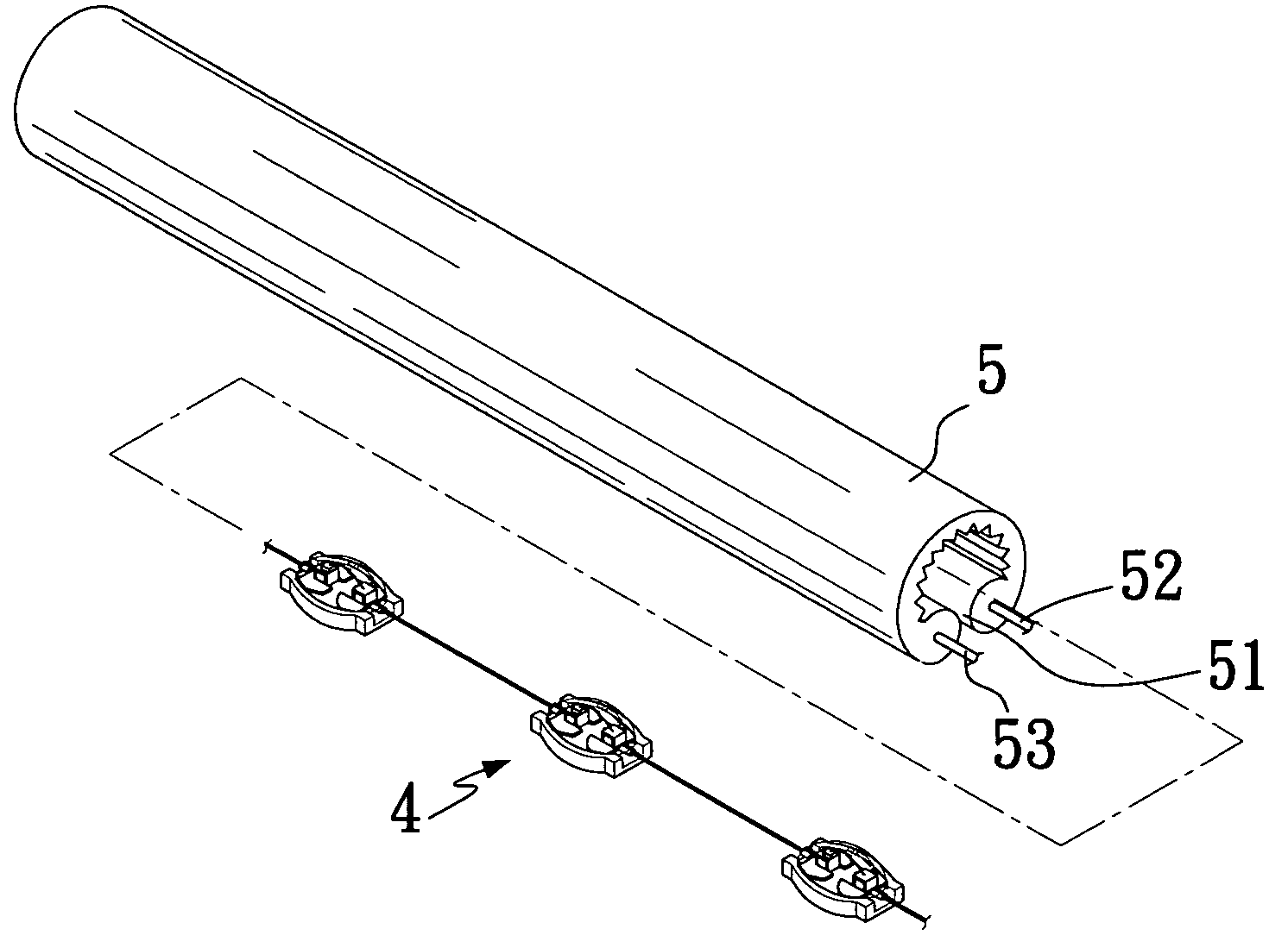
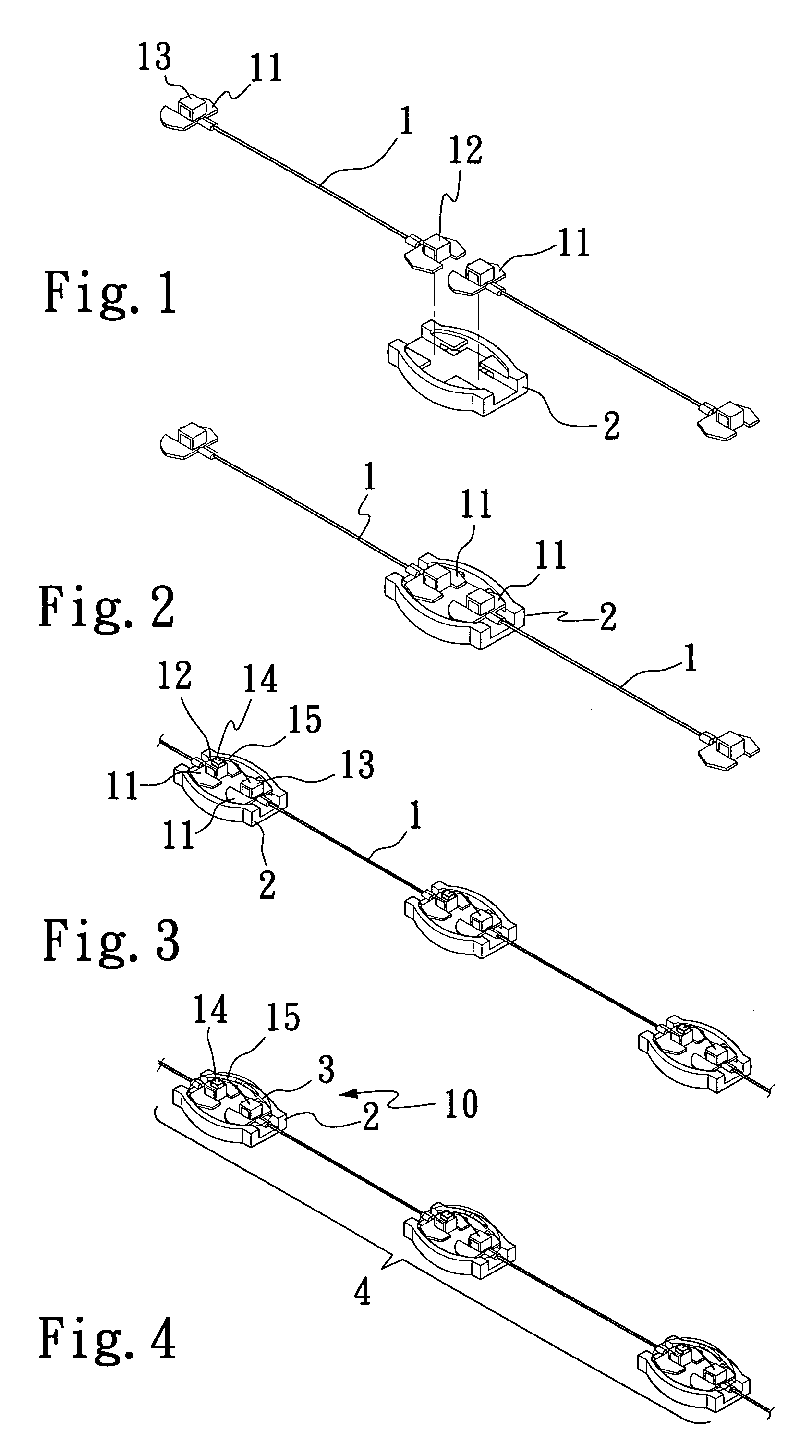
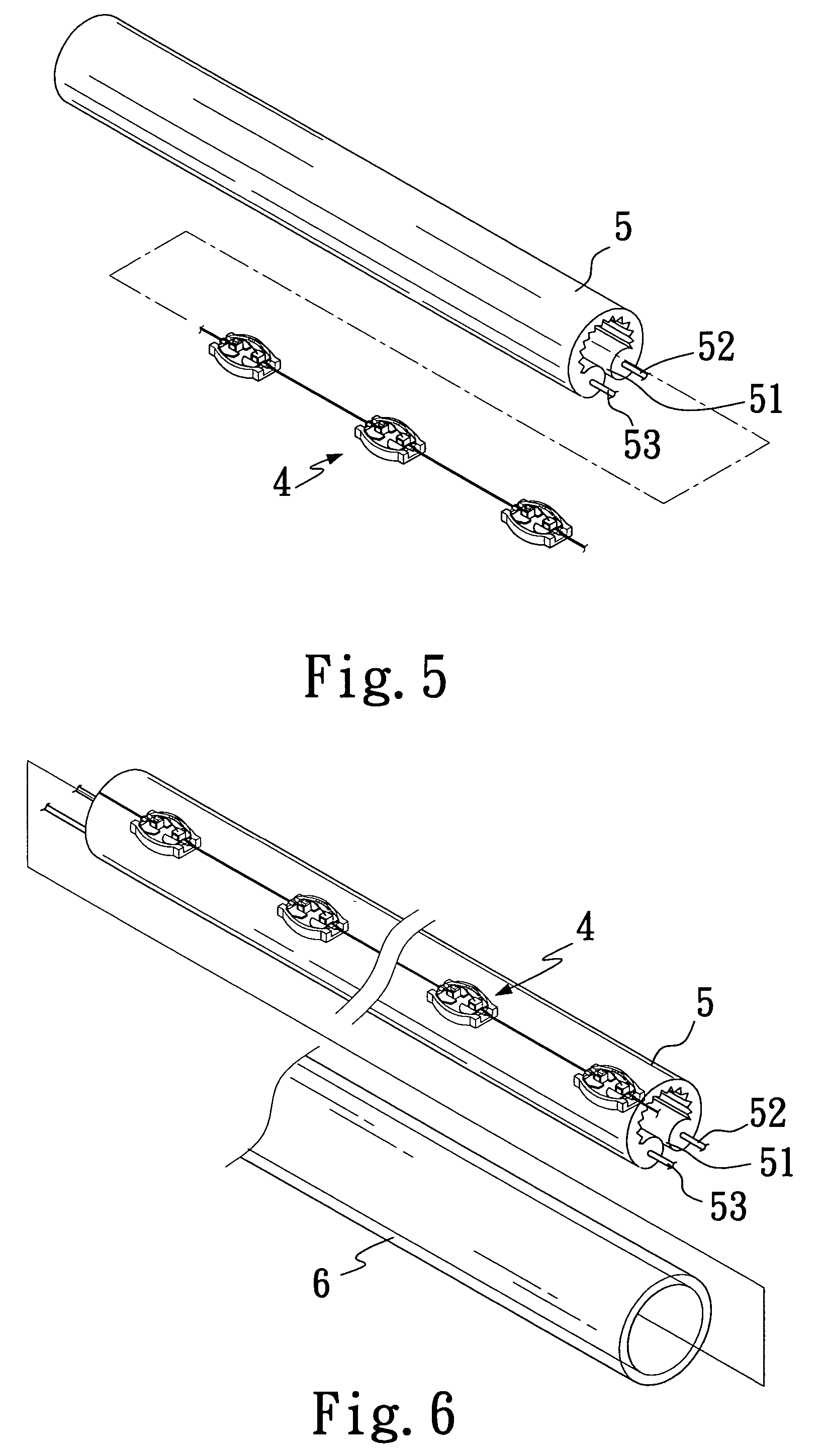
[0020] Please refer to FIGS. 1 to 7 that sequentially shows seven main steps included in the method of the present invention for producing an LED rope light.

[0021] In the first step of the method of the present invention as shown in FIG. 1, a plurality of metal wires 1 each having two silver-plated conductive terminals 11 connected to two ends thereof are prepared. The two conductive terminals 11 of each of the metal wires 1 are respectively provided on the same side with a first and a second conductive protrusion 12, 13 that have different shapes to distinctively indicate a positive and a negative polarity of the two conductive terminals 11. In the illustrated embodiment, the first and the second protrusions 12, 13 are square and round in shape, respectively.

[0022] In the second step of the method of the present invention as shown in FIG. 2, two conductive terminals 11 of different polarities on two metal wires 1 are symmetrically positioned in a light seat 2.

[0023] In the third...


PUM


Abstract

A method for producing an LED rope light mainly includes the steps of providing first and second protrusions on two conductive terminals of each metal wire to distinctively indicate positive and negative polarities thereof; serially connecting a plurality of LED lamps to form an LED light string; associating the LED light string with a power cord holder; and positioning the power cord holder with the LED light string in an outer tube having a corrugated inner wall surface. When the LED light string is supplied with power, light emitted from the LED lamps is refracted by the corrugated inner wall surface of the outer tube to provided expanded illuminating areas and softened light.

Description

FIELD OF THE INVENTION [0001] The present invention relates to a method of producing an LED rope light, of which light emitted from a plurality of internal LED light strings is refracted by a corrugated inner wall surface of an outer tube of the LED rope light to provide expanded illuminating areas, and light spots are expanded to form curved and softened lighting areas. BACKGROUND OF THE INVENTION [0002] A conventional rope light includes a plurality of bulbs as its light sources. These bulbs are serially connected to one another to form one or two bulb strings, which are then set in a long core tube. The core tube is cut at an outer surface to provide a longitudinal opening, via which the bulb string or strings are positioned into the core tube. Two power cords having different polarities are embedded in two opposite sides of a wall of the core tube. The two embedded power cords are cut at staggered positions to expose bare conductors, to which lead wires of the first and the last...

Claims


Application Information

Patent Timeline
Patent Type & Authority Applications(United States)
IPC IPC(8): F21S4/00F21V7/04
CPCF21S4/007F21Y2101/02F21V19/001F21S4/26F21Y2115/10
Inventor LIU, WEI-LIENLIU, LEE-VENLIU, WARREN
Owner LIU WEI LIEN
Why Eureka
Try Eureka