
Large-Angle Lens and Large-Angle Emission LED Light Source Module

a technology of led light source module and large-angle lens, which is applied in the direction of instruments, lighting and heating apparatus, optical elements, etc., can solve the problems of low light energy utilization efficiency, insufficient light beam angle, and poor light energy distribution and utilization effect, so as to reduce improve the light-emitting angle of the lens, and minimize the probability of total reflection

Inactive Publication Date: 2013-12-05
FOSHAN NATIONSTAR OPTOELECTRONICS CO LTD
View PDF24 Cites 15 Cited by
  • Summary
  • Abstract
  • Description
  • Claims
  • Application Information

AI Technical Summary

Benefits of technology

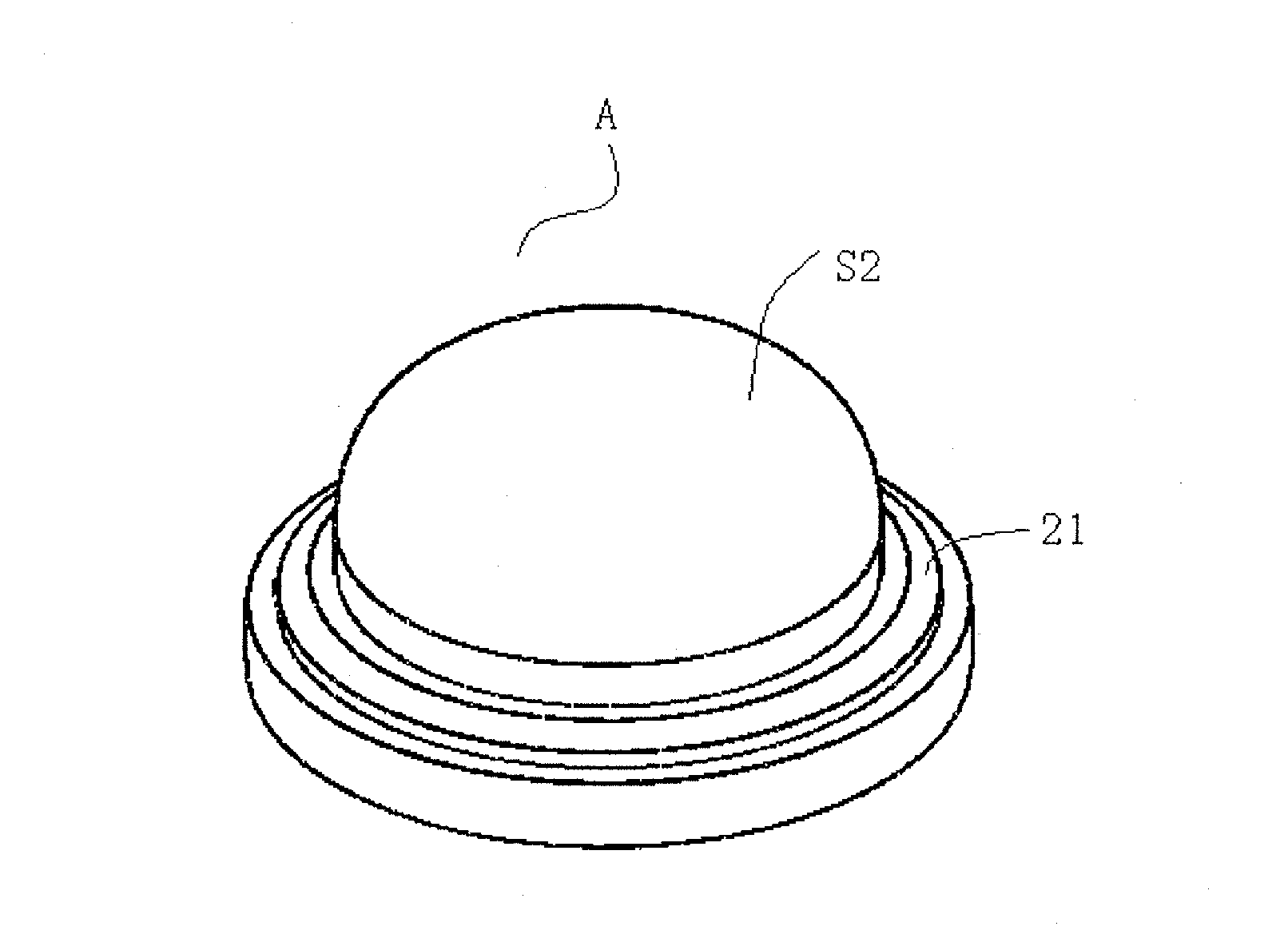
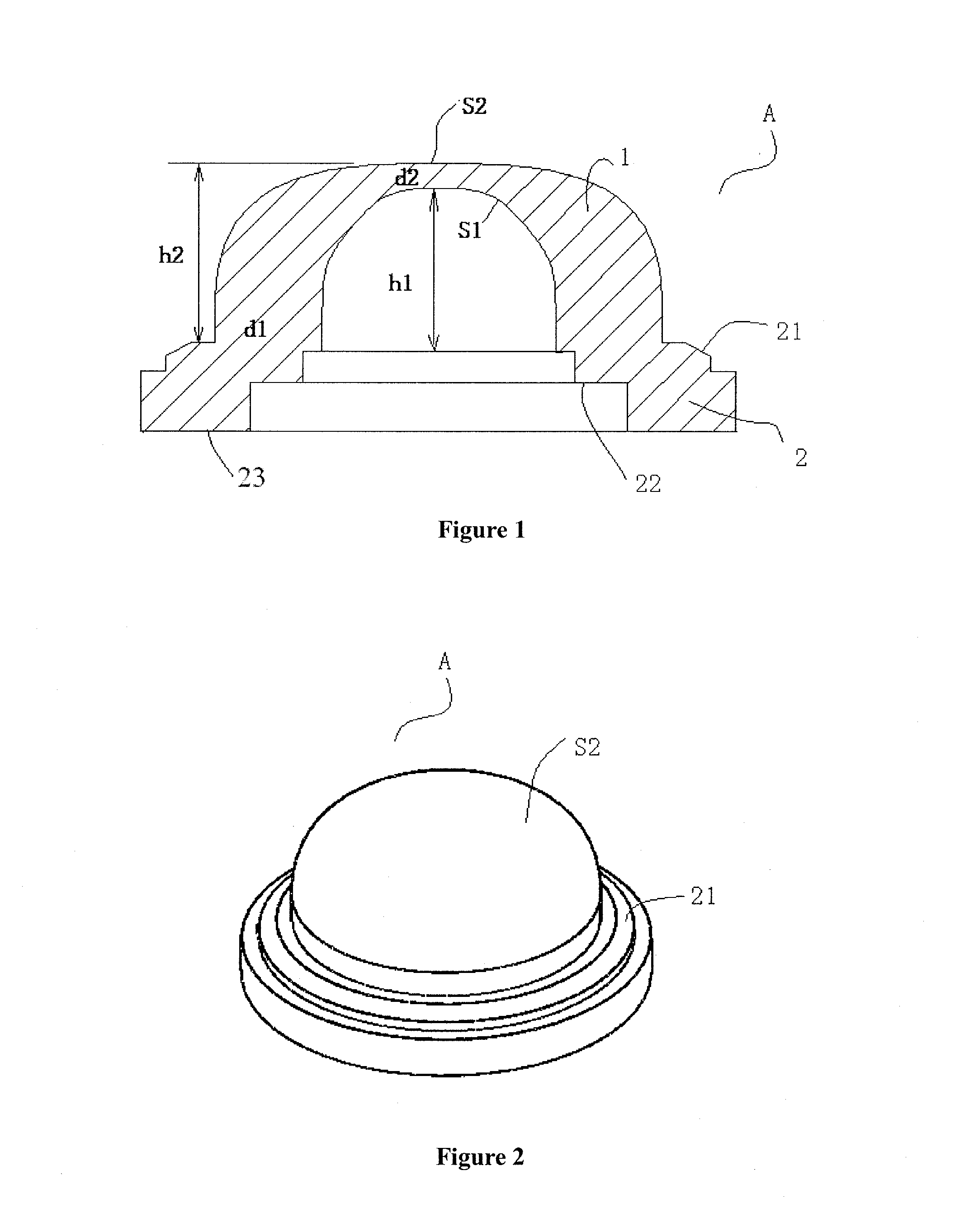
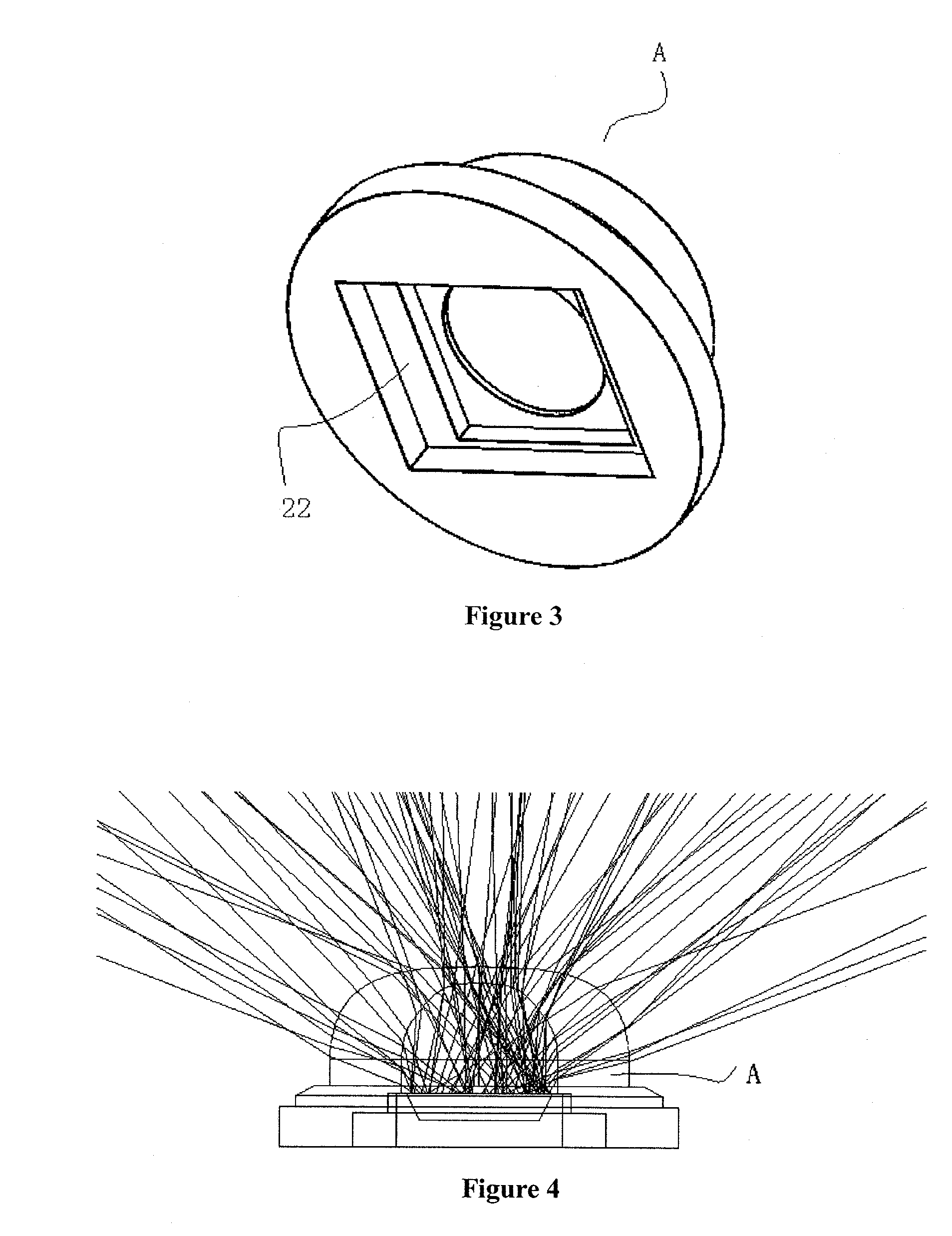
The patent text describes a new large-angle lens for LED light sources that improves the light-emitting angle and increases the illuminating area of the LED light source module. The lens has optimized its shapes and thickness settings to achieve a significantly improved light-emitting angle of up to 130°, which ensures even lighting. The lens design also minimizes total reflection, ensuring efficient light utilization, and protects the LED device from external influences. The use of the large-angle lens decreases the arranganging density of the LED light source module and reduces labor mounting costs and production costs.

Problems solved by technology

However, the light beam angle is not large enough, and the utilization efficiency of the light energy is not high.
In existing lens techniques, the effect of the light energy distribution and utilization is not very good.
As such, the technical problem to be solved presently in the prior art is how to further optimize the design of the incident surface and the exit surface of the lens to further improve the emission angle of the lens.

Method used


Image

  • Large-Angle Lens and Large-Angle Emission LED Light Source Module
  • Large-Angle Lens and Large-Angle Emission LED Light Source Module
  • Large-Angle Lens and Large-Angle Emission LED Light Source Module

Examples


first embodiment

of Large-angle Emission LED Light Source Module

[0063]Referring to FIGS. 8, 9 and 10, the large-angle emission LED light source module of this embodiment includes a substrate 4, two LED devices 5 provided on the substrate 4, a large-angle lens A, a plastic housing 3, and a power wire 6 connected to the substrate 4. Welding positions for the power wire are provided on the upper surface of the substrate 4, and a power input wire 6a and a power output wire 6b are provided at the two long edges of the upper surface of the substrate 4 respectively, thereby achieving the connection between the substrate 4 and the external power supply. An open groove 31 is formed at the outside of the plastic housing 3, and is provided around the large-angle lens A such that the exit surface of the large-angle lens A is exposed out of the bottom surface of the open groove 31 without being covered by the plastic housing 3. The side wall of the open groove 31 is composed of four inclined flat surfaces. Among...

second embodiment

of Large-angle Emission LED Light Source Module

[0069]Referring to FIGS. 15 and 16, this embodiment is different from the previous embodiment in that the large-angle lens A used has a different structure. The lens A adopted in this embodiment is of a lens structure of the large-angle lens in the second embodiment described above. Additionally, the inclined angle of the side wall flat surfaces of the open groove 31 in the plastic housing is different between this embodiment and the previous embodiment. The flat surfaces of the side wall of the open groove 31 in this embodiment each are at the same angle of 14° with respect to the bottom surface of the open groove. Alternatively, in other embodiments, this angle can also be any value within the range of 10°˜16°.

third embodiment

of Large-angle Emission LED Light Source Module

[0070]Referring to FIGS. 17 and 18, the difference between this embodiment and the above two embodiments lies in that, in this embodiment, the plastic housing 3 and the large-angle lens A are integrally manufactured with the same material through an integral forming process. In such an integral structure of the large-angle lens A and the plastic housing 3, the LED device 5 is encapsulated on the substrate 4.

[0071]Preferably, the plastic housing 3 and the large-angle lens A are made of the water-proof material.

[0072]Preferably, the light-emitting surface of the large-angle lens A is a frosted surface.

[0073]The structure of the large-angle lens A in this embodiment is similar to the structure of the large-angle lens in the third embodiment described above, in which the top of the transparent convex surface S2 includes a concave surface recessing the wall of the main body 1 rather than a flat surface, and the top of the transparent concave...


PUM


Abstract

Disclosed is a large-angle LED lens including a main body which has an incident surface on the inner side of the main body and an exit surface on the outer side thereof. The surfaces are provided symmetrically about the central axis of the main body. The incident and exit surfaces are transparent concave and convex surfaces, respectively. The maximum thickness d1 of the main body at the lower part and the minimum thickness d2 thereof at the top satisfy the relation: 4<d1 / d2<6; the concave depth h1 of the concave surface and the thickness d2 satisfy the relation: h1>4*d2; and the convex height h2 of the convex surface and the thickness d2 satisfy the relation: h2>5*d2. With the disclosure, the light-emitting angle is increased while maximizing the utilization of the light. A large-angle emission LED light source module is also disclosed herein.

Description

[0001]The present application claims the benefit of priority to Chinese patent application No. 201210183866.1 titled “LARGE-ANGLE LENS AND LARGE-ANGLE EMISSION LED LIGHT SOURCE MODULE”, filed with the Chinese State Intellectual Property Office on Jun. 5, 2012. The entire disclosures thereof are incorporated herein by reference.STATEMENT REGARDING FEDERALLY SPONSORED RESEARCH OR DEVELOPMENT[0002]Not applicable.BACKGROUND[0003]1. Field of the Invention[0004]The present disclosure relates to the field of LED encapsulation technology, and in particular to a large-angle lens and a large-angle emission LED light source module provided with the large-angle lens.[0005]2. Background of the Technology[0006]The LED light source has been paid attention to and applied widely at present due to its numerous advantages, such as small volume, low power consumption, long service life, high brightness and small heat. Therefore, the LED light source technique has been rapidly developed, and efforts hav...

Claims


Application Information

Patent Timeline
Patent Type & Authority Applications(United States)
IPC IPC(8): F21V5/04
CPCF21V5/004G02B19/0014G02B19/0061G02B19/0071G02B27/0927G02B27/0955H01L33/58
Inventor HUANG, YANGCHENGWEI, CUIEWANG, GUILINLU, WEIXIANWU, CHANGQINGHUANG, SHUNGUO
Owner FOSHAN NATIONSTAR OPTOELECTRONICS CO LTD
Learn More