Light Guiding System, Edge-Lighting Backlight Module and Liquid Crystal Display

a backlight module and light guiding technology, applied in the field of liquid crystal display, can solve the problems of large luminance difference between the front the light output end (the left side and the right side of the light output end), severe damage to the optical quality inability to adjust the brightness of the backlight module, etc., to achieve the effect of reducing the utilization of common powered light sources, saving power, and broadening the light-emitting angl

Inactive Publication Date: 2014-10-09
SHENZHEN CHINA STAR OPTOELECTRONICS TECH CO LTD
View PDF0 Cites 6 Cited by
  • Summary
  • Abstract
  • Description
  • Claims
  • Application Information

AI Technical Summary

Benefits of technology

[0015]In contrast to the related art, the present invention light guiding system, edge-lighting backlight module, and LCD utilize ambient lights as a backlight source of the backlight module. This can reduce the utilization of common powered light sources and save the power. Furthermore, the light guiding system utilizes a light diffusion device to broaden the light-emitting angle of the light output end such that the uniformity of the light output end can be improved and the optical quality of the edge-lighting module is raised.

Problems solved by technology

However, because the light-generating angle of the output end of the optical fiber is small, the luminance difference between the front of the light output end and the light output end (the left side and the right side of the light output end) is huge.
This luminance difference may be very obvious to form imbalances.
In a worst case, the position of every light output end can be distinguished and the optical quality of the backlight module is severely ruined.

Method used


Image

  • Light Guiding System, Edge-Lighting Backlight Module and Liquid Crystal Display
  • Light Guiding System, Edge-Lighting Backlight Module and Liquid Crystal Display
  • Light Guiding System, Edge-Lighting Backlight Module and Liquid Crystal Display

Examples


embodiment 1

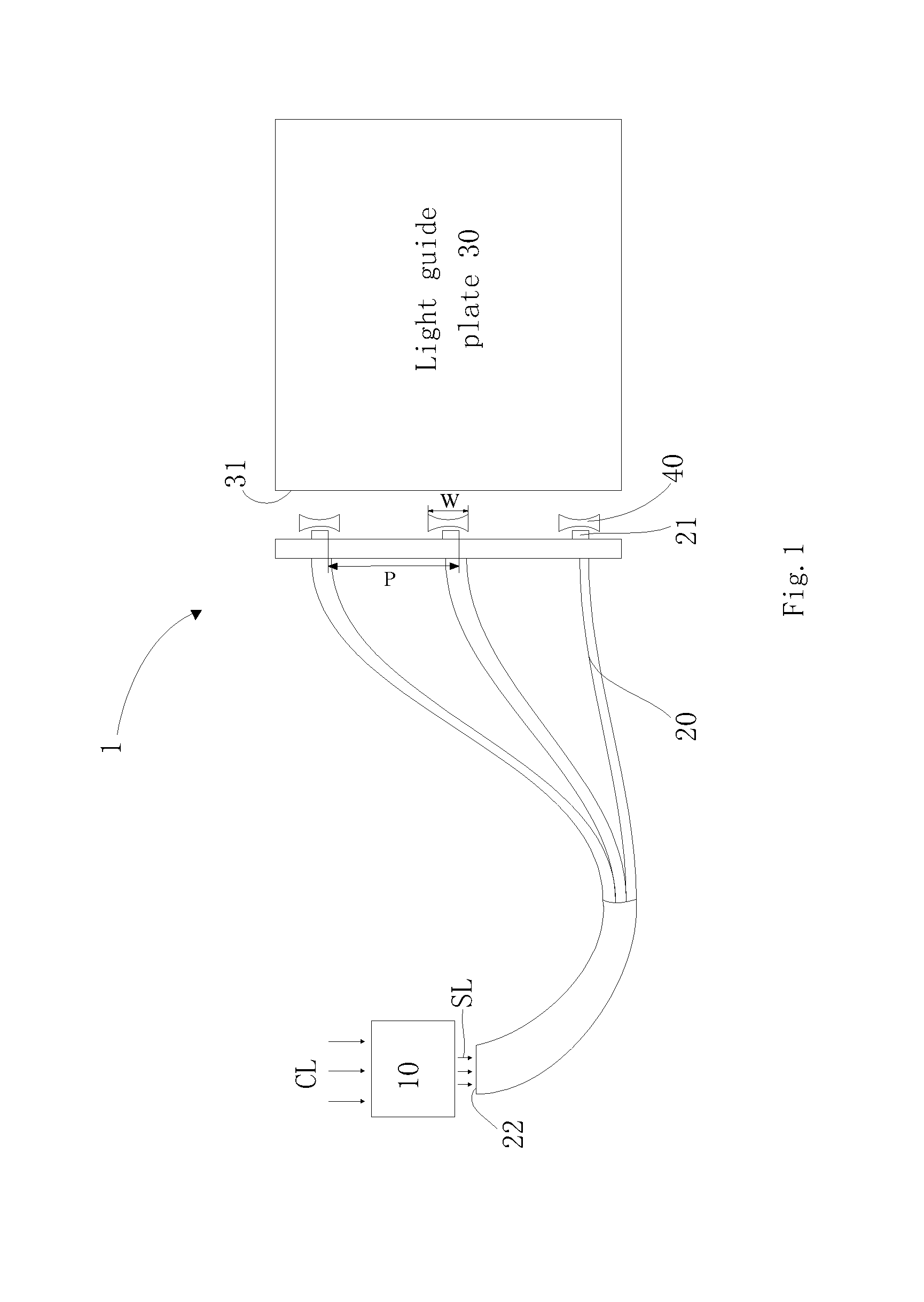
[0024]Please refer to FIG. 1. As shown in FIG. 1, the light guiding system 1 comprises an ambient light gathering system 10, a plurality of optical fibers 20, a plurality of double-concave lens 40. Specifically, the ambient light gathering system 10 fronts onto the ambient lights and absorbs the ambient lights CL, and then transforms the ambient lights CL into absorbed lights SL. Please note, the ambient lights can be emitted from the sun, light bulbs, or other light-emitting objects.

[0025]The wavelength of the absorbed lights SL lies in the range of visible lights. Therefore, the absorbed lights SL can be used as a backlight source of the backlight module. Each optical fiber 20 comprises a light output end 21 and a light input end 22. The input ends of the optical fibers 20 are collected as a bundle near the ambient light gathering system 10. The output ends of the optical fibers 20 are arranged at the output input side of the light guiding plate 30. Preferably, the light output en...

embodiment 2

[0033]Please note, in the following disclosure, only the differences between the first and the second embodiments will be illustrated, and those similar to the first embodiment will be omitted.

[0034]The light emitting diode (LED) is utilized as a common light source of the backlight module. As mentioned previously, it is powered by an outside power source. Surely, the common light source can be CCFL or any other light generating device powered by an outside power source.

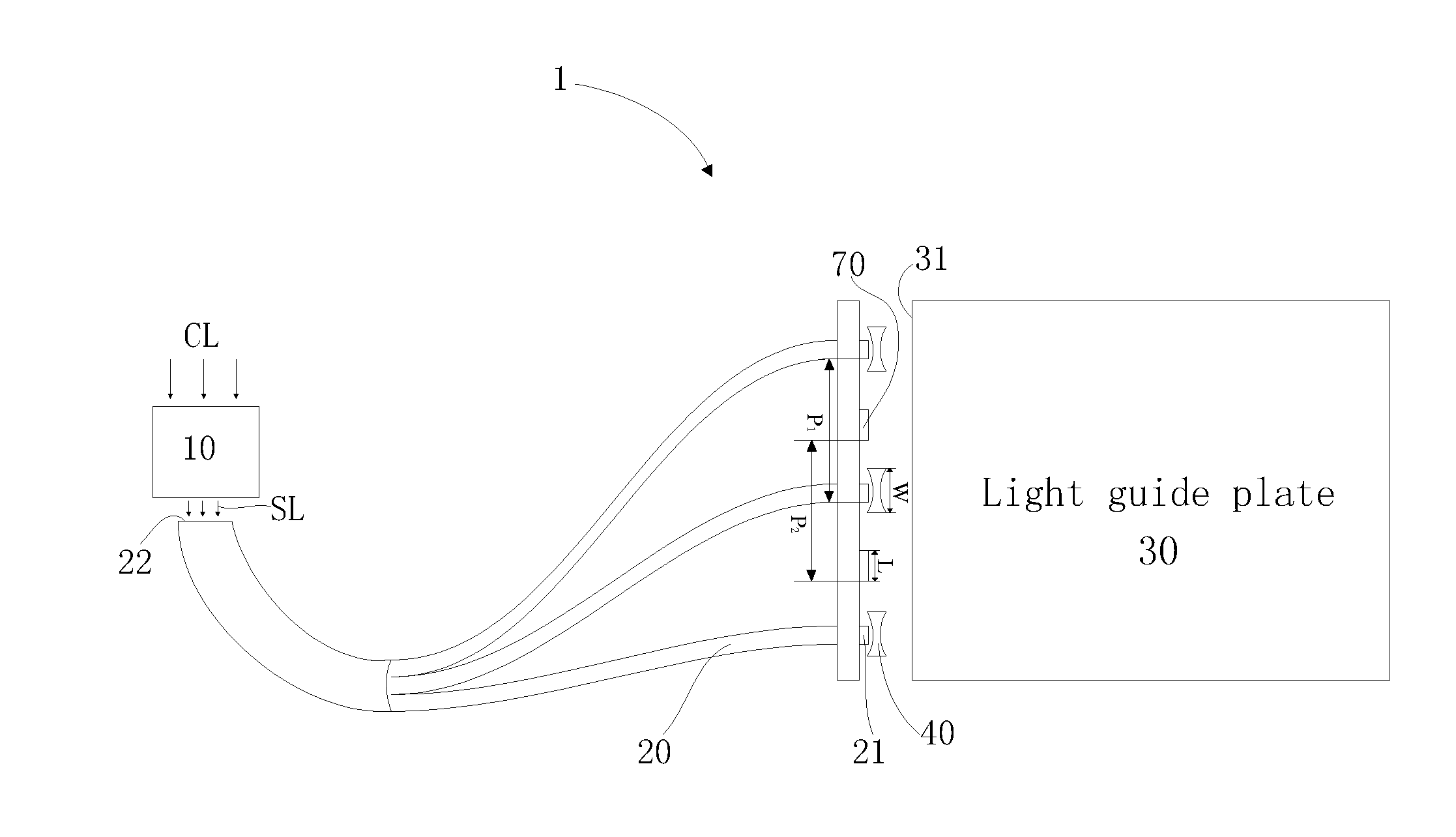
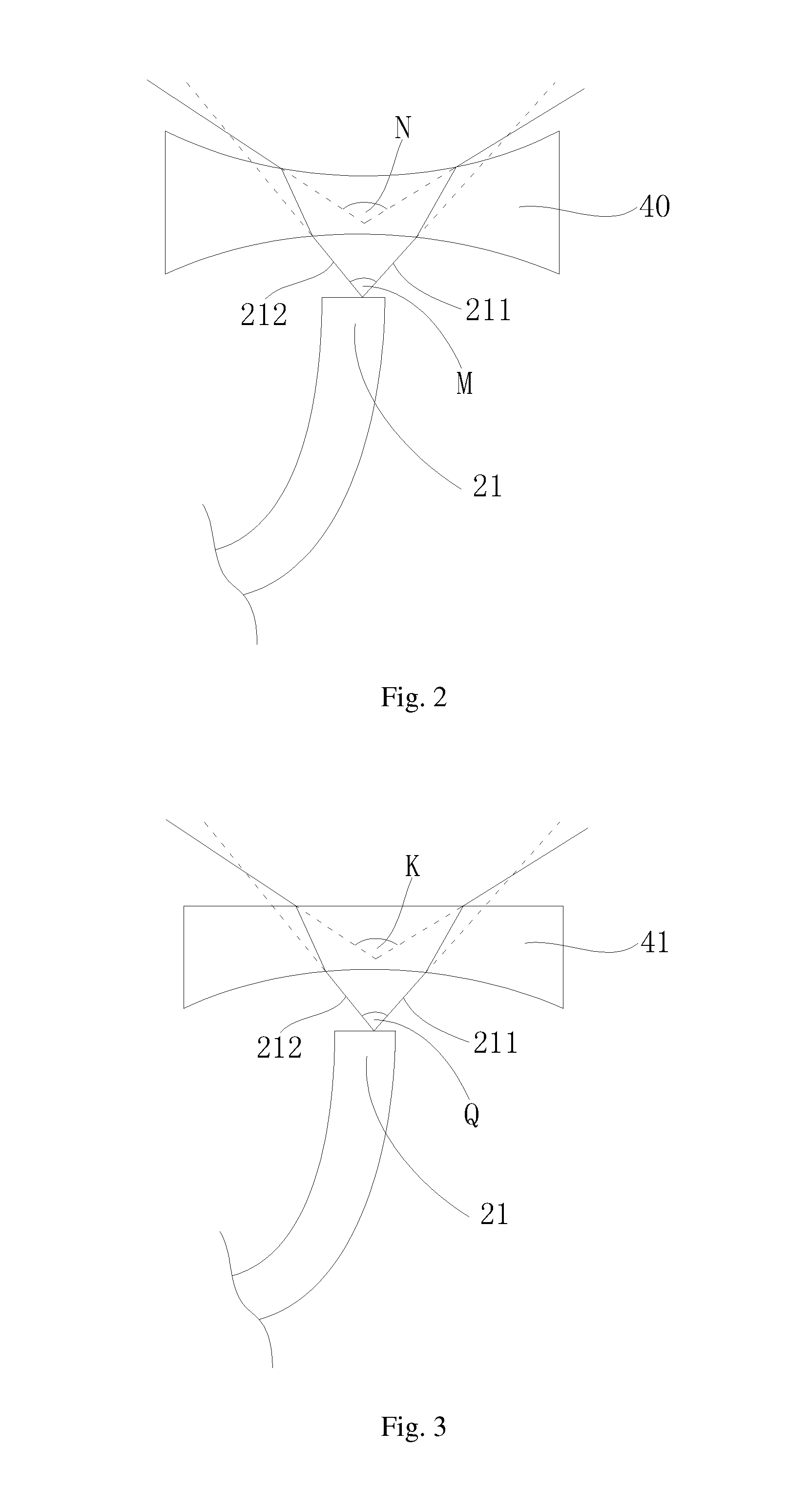
[0035]Please refer to FIG. 5. The light guiding system 1 further comprises a plurality of LEDs 70. The LEDs 70 and the light output ends 21 are arranged alternatively, and a double-concave lens 40 is established between the light output end 21 and the incident side 31. Similarly, the double-concave lens 40 can be replaced by the plano-concave lens 41. In this way, the LEDs 70 and light output ends 21 are combined together as the backlight source.

[0036]Please note, in order to broaden the light-emitting angle of the l...


PUM

PropertyMeasurementUnit
light-emitting angleaaaaaaaaaa
widthaaaaaaaaaa
power consumptionaaaaaaaaaa

Abstract

A light guiding system includes an ambient light gathering system for absorbing the ambient light to generate absorbed light; multiple light guiding devices each of which includes a light input end near the ambient light gathering system and a light output end near an incident side of a light guiding plate, and multiple light diffusion devices between the light output end and the incident side of the light guiding plate, for broadening a light-emitting angle of the light output end. The absorbed light enters the light input end and is guided to the light output end to form a backlight source. The light guiding system utilizes a light diffusion device to broaden the light-emitting angle of the light output end such that the light uniformity of the light output end is improved and the optical quality of the edge-lighting backlight module is raised.

Description

BACKGROUND OF THE INVENTION[0001]1. Field of the Invention[0002]The invention relates to a liquid crystal display, and more particularly, to a light guiding system, edge-lighting backlight module and related liquid crystal display.[0003]2. Description of the Prior Art[0004]Recently, most of the liquid crystal displays (LCD) utilizes a light source as a backlight source in the backlight module. Here, the light source means a light source consuming power to generate lights, such as light emitting diode (LED). As is known, LED has a very good light emitting efficiency with low power consumption, and is therefore widely used as the light source in the backlight module. However, according to the power saving and environment concerns, the power consumption of the backlight source has to be reduced further, the number of LED should be reduced or a new low-power light source should be developed and used in the backlight module.[0005]For example, a novel solution is to utilize the ambient li...

Claims


Application Information

Patent Timeline
Patent Type & Authority Applications(United States)
IPC IPC(8): F21V8/00G02F1/1335
CPCG02F1/133G02B6/0008G02F2001/133618G02F1/133524G02F1/1336G02B6/0011G02B6/0006G02B6/0028G02B6/0068G02F1/133615G02F1/133618
Inventor HU, CHE-CHANGHE, HU
Owner SHENZHEN CHINA STAR OPTOELECTRONICS TECH CO LTD
Why Eureka
Try Eureka