Optical filter device, optical module, and electronic apparatus

Active Publication Date: 2013-03-28
SEIKO EPSON CORP
View PDF2 Cites 16 Cited by
  • Summary
  • Abstract
  • Description
  • Claims
  • Application Information

AI Technical Summary

Benefits of technology

[0039]According to this aspect of the invention, similarly to the above aspect of the invention, the airtightness of the internal space of the inside of the housing is preferable, and the invasion of water particles and electrically-charged particles can be prevented. Therefore, the deterioration of the reflecting f

Problems solved by technology

Although JP-A-2008-70163 discloses (e.g., FIG. 6) the configuration in which the window section is fitted in the hole in the upper surface of the cap regarding the method of providing the window section, it fails to disclose other specific configurations.
In the configuration disclosed in FIG. 6 of JP-A-2008-70163, there is a problem that it is not possible to sufficiently assure the airtightness of the seal between the window section and the hole.
Thus, for example, if the inside of the package is desired to be kept at a reduced-pressure, air may enter the inside through a gap between the window section and th

Method used


Image

  • Optical filter device, optical module, and electronic apparatus
  • Optical filter device, optical module, and electronic apparatus
  • Optical filter device, optical module, and electronic apparatus

Examples


first embodiment

[0054]A first embodiment of the invention will hereinafter be explained with reference to the accompanying drawings.

1. Configuration of Optical Filter Device

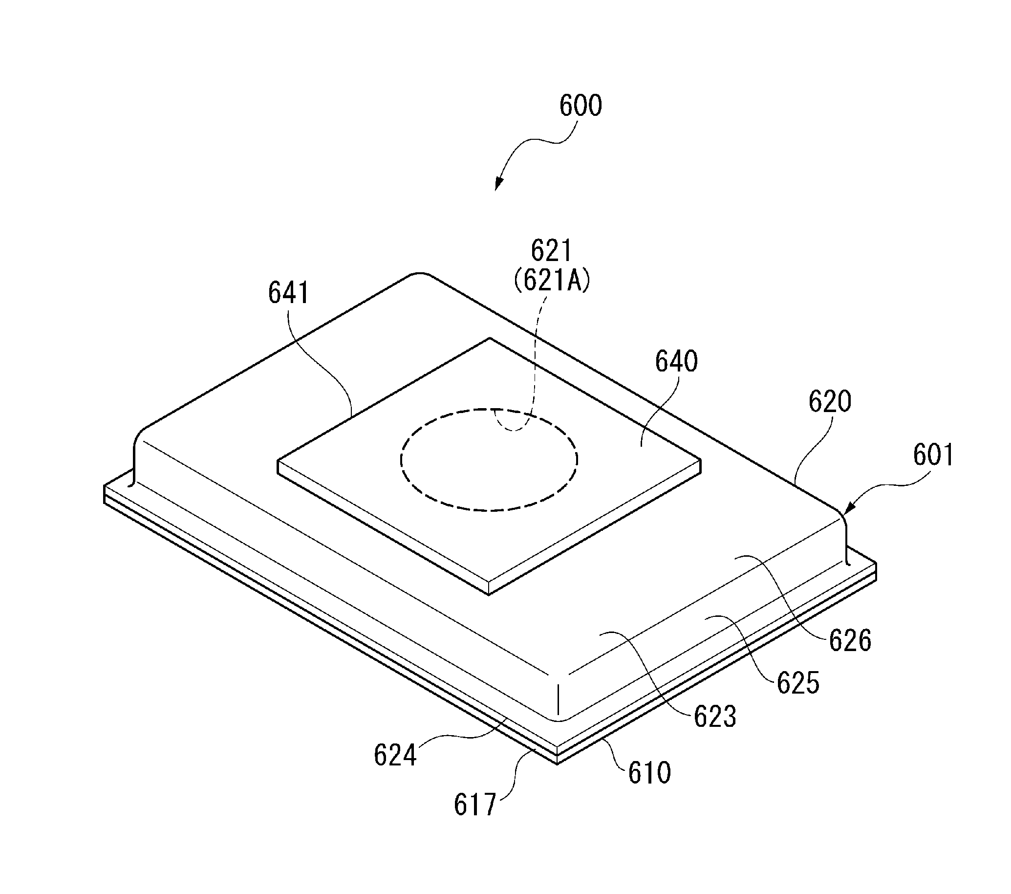
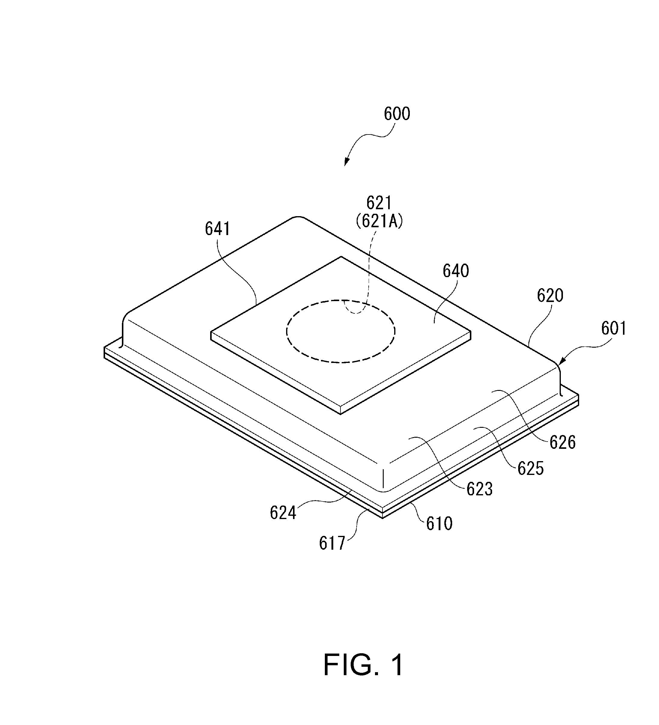
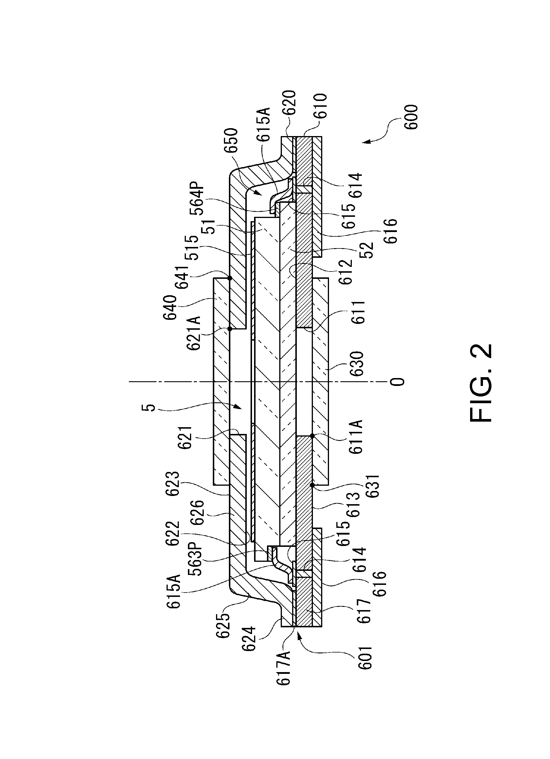
[0055]FIG. 1 is a perspective view showing a schematic configuration of an optical filter device 600 according to the present embodiment of the invention. FIG. 2 is a cross-sectional view of the optical filter device 600.

[0056]The optical filter device 600 is a device for taking out light with a predetermined target wavelength from incident test target light and then emitting the light thus emitted, and is provided with a housing 601, and a variable wavelength interference filter 5 (see FIG. 2) housed in the housing 601. Such an optical filter device 600 can be incorporated in an optical module such as a colorimetric sensor, or an electronic apparatus such as a colorimetric device or a gas analyzing device. It should be noted that the configurations of the optical module and the electronic apparatus equipped with the optical fil...

second embodiment

[0156]Next, a second embodiment of the invention will be explained with reference to the accompanying drawings.

[0157]In the second embodiment, a colorimetric sensor 3 as an optical module incorporating the optical filter device 600 according to the first embodiment described above, and a colorimetric device 1 as an electronic apparatus incorporating the optical filter device 600 will be explained.

1. Schematic Configuration of Colorimetric Device

[0158]FIG. 8 is a block diagram showing a schematic configuration of a colorimetric device 1 according to the second embodiment.

[0159]The colorimetric device 1 is an example of an electronic apparatus. As shown in FIG. 8, the colorimetric device 1 is provided with a light source device 2 for emitting light to a test object X, the colorimetric sensor 3, and a control device 4 for controlling an overall operation of the colorimetric device 1. Further, the colorimetric device 1 is a device for making the light, which is emitted from the light so...

modified examples

[0176]It should be noted that the invention is not limited to the embodiments described above, but includes modifications, improvements, and so on within a range where the advantages of the invention can be achieved.

[0177]For example, although in the first embodiment the optical filter device 600 having the internal space 650 kept in the vacuum state is manufactured by bonding the base substrate 610 and the lid 620 to each other in a vacuum, the invention is not limited thereto.

[0178]FIG. 9 is a cross-sectional view showing an optical filter device according to a modified example.

[0179]As shown in FIG. 9, the optical filter device 600A has a hole 627 in a part of the lid 620, the hole 627 for allowing the internal space 650 and the external space to communicate with each other. The hole 627 is formed so that the shape of at least the part of the hole adjacent to the base exterior surface 613 is circular. Further, the hole 627 is sealed by installing a metal ball 628 (a seal member) ...


PUM


Abstract

An optical filter device includes a variable wavelength interference filter having a stationary substrate, a movable substrate, a stationary reflecting film, and a movable reflecting film, and a housing adapted to house the variable wavelength interference filter therein. The housing has a base substrate, a lid bonded to the base substrate, and forming an internal space between the base substrate and the lid, and a lid-side glass substrate adapted to block a light passage hole provided to the lid. Further, the lid-side glass substrate has a substrate edge located outside the outer peripheral edge of the light passage hole, and is bonded to the lid in an area extending from the outer peripheral edge of the light passage hole to the substrate edge.

Description

BACKGROUND[0001]1. Technical Field[0002]The present invention relates to an optical filter device, an optical module, and an electronic apparatus.[0003]2. Related Art[0004]In the past, there has been known an interference filter having reflecting films respectively disposed on surfaces of a pair of substrates so as to be opposed to each other across a predetermined gap, the surfaces being opposed to each other. Further, there is known an optical filter device having such an interference filter housed in a housing (see, e.g., JP-A-2008-70163).[0005]The optical filter device described in JP-A-2008-70163 is provided with a package (a housing) having a plate-like pedestal and a cylindrical cap. The housing has a peripheral edge portion of the pedestal and one end portion of the cylinder of the cap connected to each other by welding or bonding, and a space for housing the interference filter is disposed between the pedestal and the cap. Further, the cap is provided with a hole disposed o...

Claims


Application Information

Patent Timeline
IPC IPC(8): G02B5/28H01L31/0232G02B7/00
CPCG02B26/001G01J3/51G01N21/31G01J3/26
Inventor MATSUNO, YASUSHITANAKA, SHUICHISANO, AKIRA
Owner SEIKO EPSON CORP
Why Eureka
Try Eureka